Advertisement
Quick Links
Advertisement

Related Manuals for Extreme Flight 60 EXTRA 300 EXP


Summary of Contents for Extreme Flight 60 EXTRA 300 EXP
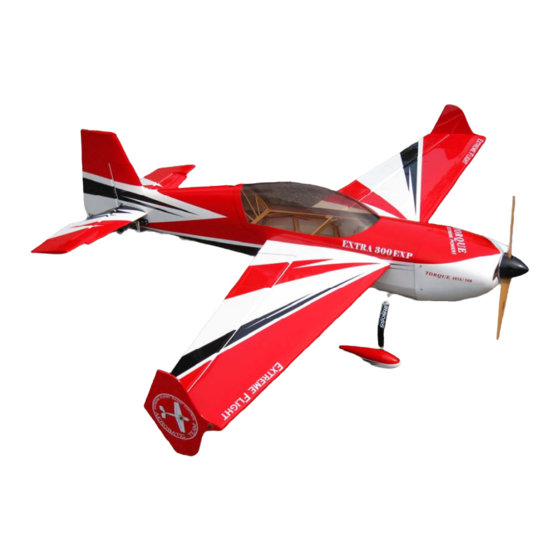
- Page 1 EXTRA 300 60 inch electric ARF assembly manual 1 ...
- Page 2 Red/white/black color scheme: True Red, White, Black Extreme Flight R/C reserves the right to alter the assembly process at any time. While we do our best to update the manuals, sometimes there are minor changes in the process of the build.
-
Page 3: Box Contents
Box contents 3 ... - Page 4 Tips for Success: 1. Before starting assembly, take a few minutes to read the entire instruction manual to familiarize yourself with the assembly process. 2. Please take a few minutes and go over all the seams on the aircraft with a covering iron on a medium heat setting.
- Page 5 Items needed for completion -Masking tape. -Hobby knife with #11 blades. -Razor saw. -Hobby sealing iron. -Thin and medium CA. We highly recommend Mercury M5T thin and M100XF medium formulas as well as the Mercury glue tips. -30 minute epoxy. The new Mercury Adhesives Epoxies have worked very well for us. -Denatured alcohol.
- Page 6 Let's begin! 1. Locate the 2 wing panels with ailerons as well as the 2 G10 aileron control horns and base plates. Remove the covering over the slot for the aileron horn on the bottom of the aileron with a sharp hobby blade. Make sure you are doing this on the bottom of the aileron! Insert the horn into the base plate and into the slot in the aileron.
- Page 7 3. Use a sharp hobby blade to remove the covering 1/16 of an inch inside the line you traced around the control horn base. 4. Mix up a batch of 30 minute epoxy and apply liberally to the slot in the aileron and to the scuffed portion of the control horn that will insert into the aileron.
- Page 8 5. Remove the covering from the aileron servo location and make sure the hinges are centered in their slots. Slide the aileron into position making sure the outer tip of the aileron is flush with the wing tip. Apply a drop of CA at each hinge location on both the top and bottom side of the wing.
- Page 9 6. Before installing the aileron servo take a minute and apply some CA to the servo tray and the anti-rotation pins. 7. Use the screws provided by the servo manufacturer to secure the aileron servo in the designated location. 9 ...
- Page 10 8. Locate the 2 threaded metal pushrods that are the same length and 4 ball links along with 4-2mm screws, nuts and washers. Thread the ball links onto each end of the pushrods and secure to the servo arm and control horn using the supplied hardware as shown in the picture.
- Page 11 Fuselage assembly 10. First lets assemble the landing gear unit and bolt it to the fuselage. Locate the main wheels, wheel pants, one piece carbon fiber landing gear, 4-3mm socket head cap bolts with 4 washers, 2 axles, 2 wheel collars, 2 large washers to fit the threaded portion of the axles, and 2 nylon insert locknuts.
- Page 12 12 ...
- Page 13 12. Secure the landing gear to the fuselage by inserting a 3mm bolt into a washer, through the carbon fiber gear and into the pre-installed blind nuts in the fuselage. Make sure to use a drop of blue Loctite on each bolt to prevent them from backing out. 13 ...
- Page 14 13. Next lets mount the horizontal stab. In preparation to do this we need to remove the piece of balsa at the rear of the stab slot. The factory leaves this piece intact so that the rear of the fuselage will remain true during the covering process and during transit. This is a simple process using a hobby razor saw.
- Page 15 15. Locate the horizontal stabilizer/elevator assembly. Turn it upside down on your building table and remove the covering over the right slot on the bottom of the elevator where the elevator control horn will be installed. You may need to sand the bottom of the horn so that it does not protrude through the top surface of the elevator.
- Page 16 16. Slide the elevator onto the hinges in the stabilizer and secure with thin CA. Again a fresh bottle of CA and a fine glue tip work best here 17. Insert the stabilizer into its slot and the carbon fiber wing tube into the fiberglass sleeve.
- Page 17 18. Remove the covering over the slot in the lower right side of the rudder where the rudder control horn will be installed as shown in the picture. Use caution and only remove the covering from the lower portion so as to not penetrate the covering over the open framework.
- Page 18 19. Using the same process as with the ailerons and elevator, slide the rudder onto the hinges and secure to the vertical stabilizer with thin CA. 20. Locate the carbon fiber tailwheel assembly in the hardware package. Secure the tailwheel bracket to the bottom rear of the fuselage with the provided wood screws. Make sure the pivot point of the assembly is over the hinge line of the rudder for best results.
- Page 19 21. Place the tailwheel wire in the proper position, aligned with the rudder and lock into place with the 2 set screws. 22. Use the hardware provided with the servos to install the rudder and elevator servos in their respective location in the rear of the aircraft. From the pilot's perspective the rudder servo mounts on the right side of the fuselage and the elevator servo mounts on the left side.
- Page 20 23. The rudder and elevator servo linkages assemble and are installed just like the aileron linkages. For maximum control surface travel we highly recommend using the Long Dubro Super Strength servo arms. (Dubro part #670 for Futaba, #671 for JR and #672 for Hitec) 20 ...
- Page 21 24. Lets prepare the Torque outrunner motor for mounting. First slide the provided collar over the motor shaft and secure in place with the set screw. Place a drop of blue Loctite on the threads of the set screw so that it will not back out. 25.
- Page 22 26. Secure the prop adapter using the 4 socket head cap bolts. Again blue Loctite should be applied to each bolt. 27. Mount the Torque motor using the supplied 3mm black socket head cap bolts and washers. The bolts are to be inserted into the blind nuts which are pre-installed in the motor mount plate.
- Page 23 Use a fine tipped marker to mark the location of the center of each mounting tab. Roll the tape back and slide the cowl into position. Install the Extreme Flight 63mm spinner onto the motor shaft for reference and once satisfied with the cowl position roll the tape back into place and secure the cowl.
- Page 24 29. Use nylon cable ties or Velcro to secure the ESC to the bottom or side of the motor box in front of one of the cowl inlet openings. 30. Place a strip of Velcro onto the battery tray and onto your battery and use a Velcro strap around the battery and tray to prevent the battery from being ejected during high G maneuvers.
- Page 25 31. If using the included Side Force Generators now is the time to mount them. There are 2 clear spacers the shape of the wing tip that are to be placed between the wing tip and SFG to prevent them from rubbing against the aileron. Each SFG mounts using 2 3mm bolts and 2 clear plastic washers.
- Page 26 Set-up and flying tips The CG range for the Extra starts at 4 inches from the leading edge of the wing and extends back to 4.75 inches, measured at the wing root. There is plenty of room on the battery tray to move your battery to achieve this CG location. This is a safe place to start and depending on your flying style you can adjust the position of the battery to alter the CG to accommodate your preferences.
- Page 27 Rudder: Low rate-20 degrees; 45-50% Exponential 3D rate- As much as possible; 80-90% Exponential Aileron: Low rate-15-20%; 40-45% Exponential 3D rate- As much as possible; 70-75% Exponential Again, these are my preferences, adjust to suit your flying style and preferred feel. The Extra 300 EXP is capable of performing the full range of known 3D and precision maneuvers.
Need help?
Do you have a question about the 60 EXTRA 300 EXP and is the answer not in the manual?
Questions and answers