
Related Manuals for Extreme Flight MXS-EXP


Summary of Contents for Extreme Flight MXS-EXP
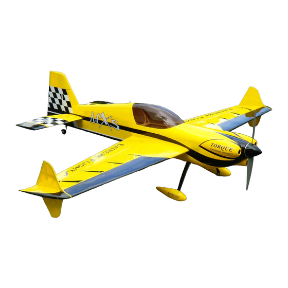
- Page 1 MXS-EXP 64 Inch Electric ARF Assembly Manual 1 ...
- Page 2 THIS IS NOT A TOY! Serious injury, destruction of property, or even death may result from the misuse of this product. Extreme Flight RC is providing you, the consumer with a very high quality model aircraft component kit, from which you, the consumer, will assemble a flying model.
- Page 3 Tips for Success: 1. Before starting assembly, take a few minutes to read the entire instruction manual to familiarize yourself with the assembly process. 2. Please take a few minutes and go over all the seams on the aircraft with a covering iron on a medium heat setting.
- Page 4 Items needed for completion -Masking tape. -Hobby knife with #11 blades. -Razor saw. -Hobby sealing iron. -Thin and medium CA. We highly recommend Mercury M5T thin and M100XF medium formulas as well as the Mercury glue tips. -30 minute epoxy. The new Mercury Adhesives Epoxies have worked very well for us. -Denatured alcohol.
- Page 5 Let's begin! 1. Locate the 2 wing panels with ailerons as well as the 2 G10 aileron control horns and base plates. Remove the covering over the slot for the aileron horn on the bottom of the aileron with a sharp hobby blade.
- Page 6 3. Use a sharp hobby blade to remove the covering 1/16 of an inch inside the line you traced around the control horn base. 4. Mix up a batch of 30 minute epoxy and apply liberally to the slot in the aileron and to the scuffed portion of the control horn that will insert into the aileron.
- Page 7 5. Remove the covering from the aileron servo location and make sure the hinges are centered in their slots. Slide the aileron into position making sure the outer tip of the aileron is flush with the wing tip. Apply a drop of CA at each hinge location on both the top and bottom side of the wing. Use a fresh bottle of thin CA and a fine glue tip for best results.
- Page 8 6. Before installing the aileron servo take a minute and apply some CA to the servo tray, root rib and the anti-rotation pins. 7. Use the screws provided by the servo manufacturer to secure the aileron servo in the designated location with the output shaft toward the leading edge of the wing.
- Page 9 8. Locate the 2 threaded metal pushrods that are the same length and 4 ball links along with 4-2mm screws, nuts and washers. Thread the ball links onto each end of the pushrods and secure to the servo arm and control horn using the supplied hardware as shown in the picture. Use the second longest set of servo arms included with the Dubro Long Super Strength servo arm kit for the aileron linkages.
-
Page 10: Fuselage Assembly
Fuselage assembly 10. First lets assemble the landing gear unit and bolt it to the fuselage. Locate the main wheels, wheel pants, one piece carbon fiber landing gear, 4-3mm socket head cap bolts with 4 washers, 2 axles, 2 wheel collars, 2 large washers to fit the threaded portion of the axles, and 2 nylon insert locknuts. - Page 11 11 ...
- Page 12 12. Secure the landing gear to the fuselage by inserting a 3mm bolt into a washer, through the carbon fiber gear and into the pre-installed blind nuts in the fuselage. Make sure to use a drop of blue Loctite on each bolt to prevent them from backing out.
- Page 13 14. Slide the horizontal stabilizer into place. Slide the carbon fiber wing tube into place to use as a reference to ensure that the stab is properly aligned. Use a ruler to make sure the stab is centered in the slot.
- Page 14 15. Slide the elevator onto the hinges in the stabilizer and secure with thin CA. Again a fresh bottle of CA and a fine glue tip work best here. 16. Glue the rudder control horn into place as you did with the aileron and elevator horns. Slide the rudder onto the hinges and into place and secure with thin CA.
- Page 15 17. Locate the carbon fiber tailwheel assembly in the hardware package. Secure the tailwheel bracket to the bottom rear of the fuselage with the provided wood screws. Make sure the pivot point of the assembly is over the hinge line of the rudder for best results. Secure the tiller using the provided screw, but do not over tighten as the tiller should be able to move on the screw as the rudder is deflected.
- Page 16 18. Use the hardware provided with the servos to install the rudder and elevator servos in their respective locations in the rear of the aircraft. The rudder and elevator servo linkages assemble and are installed just like the aileron linkages. For maximum control surface travel we highly recommend using the Long Dubro Super Strength servo arms.
- Page 17 19. Lets prepare the Torque outrunner motor for mounting. First slide the provided collar over the motor shaft and secure in place with the set screw. Place a drop of blue Loctite on the threads of the set screw so that it will not back out. 20.
- Page 18 21. Secure the prop adapter using the 4 socket head cap bolts. Again blue Loctite should be applied to each bolt. 22. Mount the Torque motor using the supplied 4mm black socket head cap bolts and washers. The bolts are to be inserted into the blind nuts which are pre-installed in the motor mount plate. Be sure to put a drop of blue Loctite onto each bolt to prevent them from backing out.
- Page 19 23. Mount your ESC on the bottom of the motor box and secure all wires with Velcro or nylon cable ties. 24. For quick, easy and accurate mounting of the cowl we recommend the following method. Tear 4 short pieces of masking tape from a roll. Place each piece of tape on the side of the fuselage so that each piece corresponds with one of the 4 cowl mounting tabs.
- Page 20 25. Place a strip of Velcro onto the battery tray and onto your battery and use a Velcro strap around the battery and tray to prevent the battery from being ejected during high G maneuvers. Mount your receiver on the portion of the battery tray that extends behind the wing tube with Velcro. 20 ...
- Page 21 26. If using the included Side Force Generators or racing wing tips or both now is the time to mount them. There are 2 clear spacers the shape of the wing tip that are to be placed between the wing tip and SFG or racing tip to prevent them from rubbing against the aileron.
- Page 22 Set-up and flying tips The CG range for the MXS starts at 4.5 inches from the leading edge of the wing and extends back to 5 inches, measured at the wing root. There is plenty of room on the battery tray to move your battery to achieve this CG location.
Need help?
Do you have a question about the MXS-EXP and is the answer not in the manual?
Questions and answers