Advertisement
Quick Links
Advertisement

Related Manuals for Extreme Flight 94" MXS-EXP


Summary of Contents for Extreme Flight 94" MXS-EXP
- Page 1 94" MXS-EXP ARF Assembly Manual Copyright 2015 Extreme Flight...
- Page 2 THIS IS NOT A TOY! Serious injury, destruction of property, or even death may result from the misuse of this product. Extreme Flight is providing you, the consumer, with a very high quality model aircraft component kit, from which you, the consumer, will assemble a flying model.
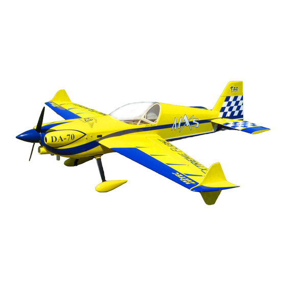
- Page 3 Congratulations on your purchase of the Extreme Flight RC 94 inch MXS-EXP ARF! The MXS is loaded with unique features, including first rate hardware, components and thorough instructions to ensure a trouble free assembly and set-up. Weight saving components are used throughout, such as carbon fiber structural reinforcement, carbon...
- Page 4 Items needed for completion: Masking tape. Hobby knife with #11 blades. Thin and medium CA. We highly recommend Mercury M5T thin and M100XF medium formulas as well as the Mercury glue tips. 30 minute epoxy. Mercury Adhesives Epoxies have worked very well for us. ...
- Page 5 Tips for Success: 1. Before starting assembly, take a few minutes to read the entire instruction manual to familiarize yourself with the assembly process. 2. Go over all the seams on the aircraft with a covering iron on a medium heat setting. Also, due to climate changes, wrinkles may develop in the covering.
-
Page 6: Let's Begin
Let's begin! Elevator Assembly 1. Locate the horizontal stabilizer/elevator assemblies as well as the composite control horns and base plates from the elevator hardware package. Use a sharp #11 blade or soldering iron to remove the covering over the 2 slots for the elevator control horns on the bottom of the elevator surface. - Page 7 3. Trace around the base plate with a felt tipped marker. 4. Remove the horn assembly and use a #11 blade to remove the covering from inside the ink line you traced around the control horn base.
- Page 8 5. Wipe away the ink line with a cotton cloth or paper towel soaked in denatured alcohol. 6. Use sandpaper to scuff the portion of the horns and base plate that will be inserted into the elevator.
- Page 9 7. Apply 30 minute epoxy to the elevator slots using a zip tie to ensure the slots are filled will epoxy. 8. Also, apply a generous amount of epoxy to the bottom of the G-10 control horns and base plate.
- Page 10 9. Reinsert the assembly into the elevator and wipe away any excess epoxy with a cloth and denatured alcohol. Place a 3mm bolt through the horns to help insure proper alignment and set aside to dry. Repeat for the other elevator half. 10.
- Page 11 11. Use a cotton swab to apply petroleum jelly ONLY to the knuckle of the hinge. This will keep the epoxy from getting into the hinge which can cause it to bind. 12. Mix a generous batch of 30 minute epoxy. Use a zip tie or an old pushrod to thoroughly coat and fill the hinge holes on the stab with epoxy.
- Page 12 13. Next, coat one side of all 4 hinges with epoxy and push the hinges into the holes of the horizontal stab. 14. Make sure the hinge pins are centered in the hinge gap and that they pivot 90 degrees to the stab.
- Page 13 15. Now coat the other side of the hinges as well as the hinge holes in the elevator with epoxy and install the elevator onto the stab. Don’t forget to apply epoxy in the hinge holes on the stab before installing the stab to the elevator.
- Page 14 16. Use denatured alcohol and a cloth to remove all excess epoxy, especially on the hinge pin. Make sure you have full deflection in both directions – once satisfied with the results, set the surface aside to dry. After the hinges have dried thoroughly, pull on them to make sure they are properly installed.
- Page 15 18. Using the manufacturer supplied mounting hardware, install the elevator servo with the output shaft toward the rear of the stab and re-attach the servo arm.
- Page 16 19. Thread 2 of the heavy duty ball links onto one of the 2 longer titanium pushrods. Remember that the ends of the pushrods are reverse-threaded so that they can be adjusted like a turnbuckle without removing the linkage. 20. As shown in the picture below, secure one end of the ball link to the servo arm using a 3mm socket head cap screw, washer and nylon insert locknut.
- Page 17 21. With the servo arm centered (as described in Step 17), adjust the turnbuckle on the control rod until the elevator is in the neutral position. 22. Set the servo endpoints to achieve maximum travel. You may need to enlarge the size of the servo arm exit slot.
-
Page 18: Wing Assembly
Wing Assembly 23. Locate the wing/aileron assemblies as well as the composite control horns and base plates from the elevator hardware package. Following the same procedure as outlined with the elevator / stabs, install the control horns and hinges for both wings. - Page 19 Note: Before moving to the next step – it would be a good time to seal the hinge gap with a strip of Ultracote or Blenderm tape. Be sure to fully deflect the control surface when sealing the gap to allow for full deflection once the gap is sealed. Also, take a few minutes to go over the wings with a trim iron on a medium heat to seal all the trim seams and remove any wrinkles in the covering.
- Page 20 25. Attach a 12” servo extension to your servo and secure with thread or heat shrink tubing. Use the manufacturer supplied mounting hardware to install the servo with the output shaft toward the trailing edge of the wing. Electronically center the servo.
-
Page 21: Rudder And Tailwheel Assembly
26. Use the recommend 1.5” SWB servo arms and attach 2 ball links onto the titanium turnbuckle pushrod. Secure the pushrod to the control horns and servo arm using the supplied 3mm bolts, washers, and nylon insert locknuts as shown in the picture below. - Page 22 28. Locate the rudder, the rudder control horns and the 2 slotted base plates as shown in the picture below. Use sandpaper to scuff the bottom of the control arms as well as the side of the base plates that will attach to the rudder. 29.
- Page 23 30. Mix a generous batch of epoxy and completely fill the two slots as well as the areas on control horns and base plates that will glue into both sides of the rudder. 31. Install the rudder horns and base plates into the rudder one side at a time. Clean any excess epoxy from the rudder, recheck the alignment and set the assembly aside to dry.
- Page 24 32. Locate a 2mm ball link from the hardware bag. Measure 3” back from the leading edge of the rudder and drill a 3/16” hole to accept the shank on the ball link. Scuff the shaft of the ball link and glue the ball link into the hole as shown below.
- Page 25 34. Disassemble the tailwheel assembly and use a rotary tool or a small file to create a flat spot on the tailwheel wire for the set screws in the aluminum cap to seat against. Reassemble the unit and apply Loctite to the threads on the setscrews. Slide the tailwheel onto the wire and secure with the included wheel collars.
- Page 26 36. Next, install the pull-pull rudder cables. First remove the covering from the exit slots at the rear of the fuselage as shown below. 37. Locate the rudder servo and install the recommended SWB 4” offset rudder arm as shown in the picture below. Also it’s a good time to electronically center the servo.
- Page 27 38. Install the rudder servo using the supplied hardware with the output shaft toward the front of the plane. 39. Next, install the pull-pull rudder cables. Assemble one end of the linkage by inserting the pull-pull cable into one of the aluminum crimp tube, through the hole in the brass pull-pull fitting and back through the crimp tube.
- Page 28 40. Insert the bare end of the cable into the slot in the rear of the fuselage and feed it forward into the canopy area. Make the same type of linkage as done previously. Electronically center the servo and secure the linkage at both ends with a 3mm bolt and nylon insert lock nut.
- Page 29 41. Locate the Carbon Fiber main landing gear, 4 x 4mm bolts, lock nuts and washers. Place the landing gear onto the landing gear plate on the bottom of the fuse and align the 4 holes. Use a long T-Handle allen wrench and insert the 4 x 4mm bolts from inside the fuse.
- Page 30 42. Prepare the landing gear fairings by slitting the supplied black neoprene tubing length wise with a sharp hobby knife. Push the tubing onto the rim of the fairing and secure with CA.
- Page 31 43. Temporarily slide the fairing onto the gear and up against the fuselage. Place some blue painters tape at the bottom of the fairing to mark the location on the gear. Lightly sand the gear leg where the fairing will attach. 44.
- Page 32 45. Once the silicon glue has thoroughly cured, remove the blue painters tape and clean up any residual glue using denatured alcohol. 46. Locate the 2 axles, 2 locking nuts, 2 washers, 2 wheels, 4 wheel collars and 2 wheel pants. Place the threaded portion of the axle through the hole in the landing gear, place a washer onto the axle and secure the axle with a locking nut.
- Page 33 47. Install one wheel collar on the axel first in order to center the wheel in the wheel pant. Next, slide the wheel onto the axel and secure the wheel with the second wheel collar. Repeat this process for the remaining wheel. 48.
- Page 34 49. Next we’ll install the engine. We have made this process very easy. The center and offset marks have been scribed into the front of the firewall with a laser. Print out the engine mounting template for your chosen engine. 50.
- Page 35 51. Use the recommended mounting bolts to mount the engine to the firewall making sure to use large washers behind the firewall to distribute the load. Use standoffs to ensure the motor extends 6 5/16 inches from the firewall to the engine thrust washer.
- Page 36 53. Install the ignition unit and regulator on the side of the engine box or under the engine box lid using Velcro or nylon cable ties. Make sure to put a piece of foam behind the unit to prevent damage from vibration. 54.
- Page 37 55. Find a location toward the front of the fuse to install a fuel dot. Here is where we installed ours. 56. Once the throttle linkage is installed and all the plumbing is completed, install the engine box cover with 4 wood screws. You may want to take the time to install some blind nuts and use bolts for this.
- Page 38 fuselage. Since switch sizes vary, use a template to ensure you cut the proper size hole for your specific switch. Also, carefully choose the locations to mount your batteries to help achieve correct center of gravity. 58. Slide the cowl into position and align the 4 slots in the cowl ring with the mounting tabs in the fuse.
- Page 39 59. Once you’re satisfied with the fit of the cowl, add some thick CA or Epoxy to the intersection of the cowl and plywood cowl ring. Slide the cowl into position and secure with 4 x 3mm bolts and washers through the pre-drilled holes in the cowl. (2 per side) 60.
- Page 40 mounting tabs and into the pre-mounted blind nuts. Make sure to use a drop of blue Loctite on these bolts. 62. The canopy is retained by 4 x 3mm bolts and washers. Before flying the MXS run a bead of RC-56 canopy glue all along the intersection of the canopy and its wood frame, front and back and both sides.
-
Page 41: Control Surface Throws
you will agree it was time well spent. One of the most practical ways to check the CG on an aircraft this size is to insert the carbon fiber wing tube into its sleeve in the fuselage and tie a length of rope around the tube on each side of the fuselage, forming a loop that you can pick the aircraft up with. - Page 42 I get the planes to look so shiny, this is my secret. You may wish to apply all of your graphics before applying the coat of wax. Thanks again for your purchase of the Extreme Flight RC 94 inch MXS ARF. I hope you enjoy assembling and flying yours as much as I have mine.
Need help?
Do you have a question about the 94" MXS-EXP and is the answer not in the manual?
Questions and answers