Advertisement
Quick Links
Advertisement

Related Manuals for Extreme Flight GB1 GAMEBIRD EXP


Summary of Contents for Extreme Flight GB1 GAMEBIRD EXP
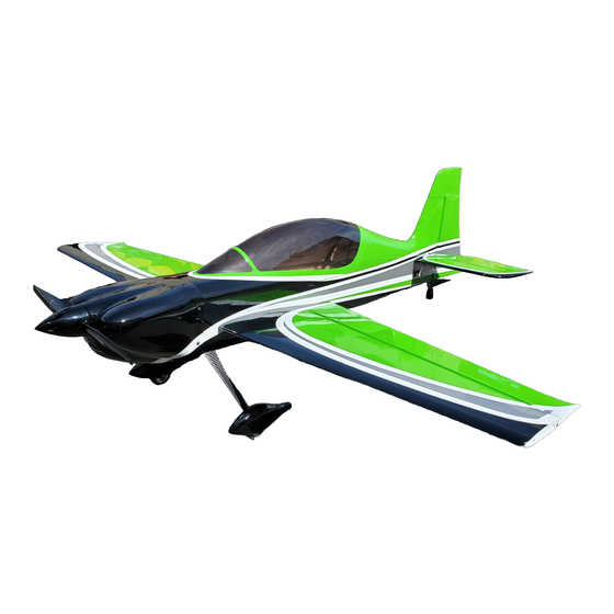
- Page 1 GAMEBIRD 60 Inch Electric ARF Assembly Manual Copyright Extreme Flight 2019...
- Page 2 Red scheme: True Red #HANU866, White #HANU870, Silver #HANU881, Black #HANU874 Extreme Flight R/C reserves the right to alter the assembly process at any time. While we do our best to update the manuals, sometimes there are minor changes in the process of the build. If you have any questions regarding assembly please check the webpage for any assembly manual addendums or contact us before moving forward.
- Page 3 THIS IS NOT A TOY! Serious injury, destruction of property, or even death may result from the misuse of this product. Extreme Flight RC is providing you, the consumer with a very high quality model aircraft component kit, from which you, the consumer, will assemble a flying model.
- Page 4 -4 mini metal geared servos. All flight testing was performed with Hitec HS-7245s, MKS 9767s and Savox 1260s. Please note that the MKS and Savox servos will require slight elongation of the servo slots. -4 Extreme Flight Anodized 1.25" lightweight servo arms. -Torque 4016T/500 Brushless Outrunner.
- Page 5 Let's begin! 1. Locate the 2 wing panels with ailerons as well as the 2 G10 aileron control horns and base plates. You will find 4 G10 control horns in the hardware package; 2 horns with longer shanks (the portion of the control horn that glues into the surface) and 2 horns with shorter shanks.
- Page 6 4. Install your choice of servo with the output spline oriented toward the trailing edge of the wing. We recommend the use of the Extreme Flight Xcessories socket head servo screws for servo mounting. Please note that some of the newer mini servos are slightly longer than the industry standard and may require a slight modification to the servo mounting plate.
- Page 7 Fuselage assembly 6. First lets assemble the landing gear unit and bolt it to the fuselage. Locate the main wheels, wheel pants, one piece carbon fiber landing gear, 2 axles, 2 wheel collars, 2 large washers to fit the threaded portion of the axles, and 2 nylon insert locknuts.
- Page 9 8. Secure the landing gear to the fuselage by inserting a 3mm bolt into a washer, through the carbon fiber gear and into the pre-installed blind nuts in the fuselage. Make sure to use a drop of blue Loctite on each bolt to prevent them from backing out.
- Page 10 9. Next lets mount the horizontal stab. In preparation to do this we need to remove the Ultracote covered filler block at the rear of the stab slot. I also find it easier to go ahead and hinge the elevator and install the control horn before gluing the stab into place.
- Page 11 10. Slide the elevator onto the hinges and secure to the horizontal stab with several drops of CA at each hinge location. Be sure to use a fresh bottle of thin CA to ensure maximum penetration and adhesion. 11. Slide the horizontal stab into position making sure to push it as far forward into the slot as possible. The alignment recess in the forward part of the stab will aid in proper positioning.
- Page 12 12. Once the glue securing the stab is dry glue the filler block back into place behind the stab. 13. Scuff the shank on the rudder control horn and glue into position with medium CA as shown.
- Page 13 14. Using the same process as with the ailerons and elevator, slide the rudder onto the hinges and secure to the vertical stabilizer with thin CA. 15. Locate the carbon fiber tailwheel assembly in the hardware package. Secure the tailwheel bracket to the bottom rear of the fuselage with the provided wood screws.
- Page 14 16. Place the tailwheel wire in the proper position, aligned with the rudder and lock into place with the set screws. 17. Attach a 24" Extreme Flight 28 AWG servo extension to the servo lead on your elevator and rudder servos and secure with an EF Servo Safety Clip or heat shrink tubing. Use the hardware provided with the servos to install the rudder and elevator servos in their respective location in the rear of the aircraft.
- Page 15 18. Attach the collar, radial mount and prop adapter to the Torque 4016T/500 and mount the motor using the supplied 4mm black socket head cap bolts and washers. The bolts are to be inserted into the blind nuts which are pre-installed in the motor mount plate. Be sure to put a drop of blue Loctite onto each bolt to prevent them from backing out.
- Page 16 19. There is a set of clear plastic baffles included in your kit. We highly recommend installing these. We've found them to keep motor temperature very low, at times even below ambient temperature. Simply trim them along the etched trim lines and glue into position as shown behind the air inlets with medium CA or Goop style glue.
- Page 17 21. Place a strip of Velcro onto the battery tray and onto your battery and use a Velcro strap around the battery and tray to prevent the battery from being ejected during high G maneuvers. Mount your receiver on the portion of the battery tray that extends behind the wing tube with Velcro. 22.
- Page 18 23. Open the carbon fiber canopy locks and disengage the spring loaded hatch latch and remove the canopy. Lift the aluminum wing retention locks into the open position. Insert the wing tube into the receptacle in the fuselage and slide the wings onto the tube and up against the fuselage sides. Push the aluminum wing retention locks into place and plug the aileron servo leads into the receiver.
- Page 19 Set-up and flying tips We have found that the ideal location for the Gamebird to balance is 5 inches from the leading edge of the wing measured at the wing root. There is plenty of room on the battery tray to move your battery to achieve this CG location although we have found that placing the battery just in front of the wing tube is typically ideal for a wide range of flying styles.
- Page 20 The Gamebird EXP is capable of performing the full range of known 3D and precision maneuvers. It is also capable of performing all kinds of crazy aggressive maneuvers that have yet to be named. A great deal of fun and excitement can be had by just gaining some speed and pushing the sticks into new positions and seeing what happens! We've been able to coax all kind of crazy gyroscopic maneuvers out of this airframe.
Need help?
Do you have a question about the GB1 GAMEBIRD EXP and is the answer not in the manual?
Questions and answers