Advertisement
Quick Links
Advertisement

Related Manuals for Extreme Flight 52’’ EXTRA 300 EXP


Summary of Contents for Extreme Flight 52’’ EXTRA 300 EXP
- Page 1 52" EXTRA 300 Electric ARF Copyright 2016 Extreme Flight...
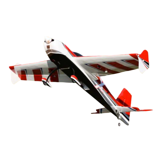
- Page 2 Greetings and congratulations on your purchase of the Extreme Flight RC 52" Extra 300 EXP ARF This new Extra is the first in a series of midsized electrics built around the new Xpwr T3910 brushless outrunner. This size aircraft delivers big plane performance in a package that is easy to transport and maintain at a very reasonable price point.
- Page 3 Tips for Success: 1. Before starting assembly, take a few minutes to read the entire instruction manual to familiarize yourself with the assembly process. 2. Please take a few minutes and go over all the seams on the aircraft with a covering iron on a medium heat setting.
- Page 4 -XOAR 14x8 or 15x7 PJN propeller. -57mm Extreme Flight spinner. -2 Extreme Flight 28awg 18"extensions for the 2 rear servos and 2 6"extensions to go between the receiver and the aileron servo leads. -Adhesive backed Velcro and Velcro strap for ESC mounting and battery retention.
- Page 5 Let's begin! 1. Locate the 2 wing panels with ailerons as well as the 2 G10 aileron control horns and base plates. Remove the ailerons from the wing and remove the covering over the slot for the aileron horn on the bottom of the aileron with a sharp hobby blade.
- Page 6 3. Use a glue tip on your bottle of medium CA and apply glue to the slot as well as to both sides of the control horn. Insert the control horn into the baseplate and then into the slot and make sure it seats properly against the surface of the aileron.
- Page 7 4. Remove the covering from the aileron servo location and make sure the hinges are centered in their slots. 5. Slide the aileron into position on the hinges and secure with several drops of fresh thin CA. This process is much easier and more effective if a fine glue tip is used.
- Page 8 2 mm hardware as shown in the picture. We recommend the use of the Extreme Flight lightweight electric servo arms as shown. Please note the orientation of the pushrod in relation to the control horn.
- Page 9 8. Locate the carbon fiber main landing gear, 2 axles, 2 locking nuts, 2 wheels, 2 wheel collars and the 2 wheel pants from the hardware package. Place the threaded portion of the axle through the hole in the carbon gear and screw the lock nut onto the axle, but do not tighten completely.
- Page 11 9. Locate the fuselage, 2-3mm socket head cap bolts and 2 washers. Secure the landing gear to the fuselage by inserting a 3mm screw into a washer, through the carbon fiber gear and into the pre-installed blind nut in the fuselage.
- Page 12 11. Insert the stabilizer into its slot and the carbon fiber wing tube into the plastic sleeve. Use a ruler to insure that the stabilizer is centered in its slot and compare the stabilizer to the wing tube to make sure it is properly aligned.
- Page 13 13. Slide the elevator onto the hinges in the stabilizer and secure with thin CA. Again a fresh bottle of CA and a fine glue tip work best here 14. Remove the covering over the slot in the lower left side of the rudder where the rudder control horn will be installed.
- Page 14 15. Using the same process as with the ailerons and elevator, slide the rudder onto the hinges and secure to the vertical stabilizer with thin CA. 16. Locate the carbon fiber tailwheel assembly in the hardware package. Secure the tailwheel bracket to the bottom rear of the fuselage with the provided wood screws.
- Page 15 Alternately you can use the Extreme Flight lightweight electric servo arm for the rudder servo, however there is not enough room below the bottom of the stab to use this arm for the elevator.
- Page 17 21. Next lets mount the Xpwr T3910 motor to the airframe. First go over all of the motorbox joints with thin CA! Secure the radial X mount and prop adapter to the motor with the supplied hardware. Use the supplied 4mm socket head cap bolts and washers to secure the motor to the front of the motor box.
- Page 18 Roll the tape back and slide the cowl into position. Install an Extreme Flight 57mm spinner onto the motor shaft for reference and once satisfied with the cowl position roll the tape back into place and secure the cowl.
- Page 19 24. Place a strip of Velcro onto the battery tray and onto your battery and use a Velcro strap around the battery and tray to prevent the battery from being ejected during high G maneuvers. Mount your receiver on the wing retention cross brace.
- Page 20 Slide the carbon fiber wing tube into the fuselage and the wings onto the tube. Secure to the fuselage using the 2 3mm bolts and washers inserted through the tabs and into the pre-installed blind nuts. Set-up and flying tips The CG range for the 52"...
- Page 21 3D flight will allow you to experience the best attributes of the Extra EXP or any aircraft for that matter. The included elevator servo arm will allow for close to 80 degrees of throw! While this is great for really aggressive tumbling maneuvers, positive and negative waterfalls and straight down dropping elevators, it can wreak havoc on stable harriers, especially if you are just learning the maneuver.
Need help?
Do you have a question about the 52’’ EXTRA 300 EXP and is the answer not in the manual?
Questions and answers