
Related Manuals for Extreme Flight 91" LASER EXP ARF


Summary of Contents for Extreme Flight 91" LASER EXP ARF
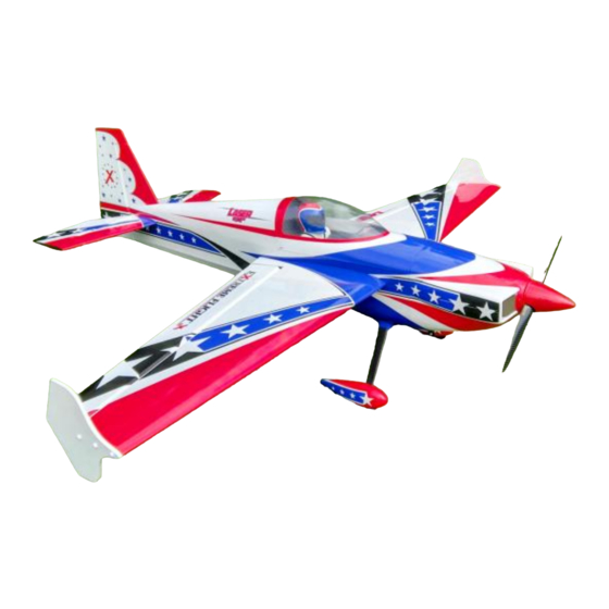
- Page 1 91" LASER EXP ARF Assembly Manual Copyright 2017 Extreme Flight...
- Page 2 THIS IS NOT A TOY! Serious injury, destruction of property, or even death may result from the misuse of this product. Extreme Flight is providing you, the consumer, with a very high quality model aircraft component kit, from which you, the consumer, will assemble a flying model.
- Page 3 Experience the evolution in 70cc aircraft design and performance! By far the most technologically advanced aircraft from Extreme Flight in this size, the new 91" Laser EXP is a marvel of modern construction techniques and unbridled aerobatic performance. Weight saving components are used throughout, such as carbon fiber structural...
- Page 4 ✓ 2 x Extreme Flight 12” 20 awg Servo Extensions. ✓ 1 24" Extreme Flight 20 awg Servo Extension. ✓ 2 x 36” Extreme Flight 20awg Servo Extensions. If you need to remove the stabs for transport use 48" extensions.
- Page 5 Tips for Success: 1. Before starting assembly, take a few minutes to read the entire instruction manual to familiarize yourself with the assembly process. 2. Go over all the seams on the aircraft with a covering iron on a medium heat setting. Also, due to climate changes, wrinkles may develop in the covering.
- Page 6 Let's begin! Elevator Assembly 1. Locate the horizontal stabilizer/elevator assemblies as well as the composite control horns and base plates from the elevator hardware package. Trial fit the assembly into the slots in the elevator. 2. Trace around the base plate with a felt tipped marker.
- Page 7 3. Remove the horn assembly and use a #11 blade to remove the covering from inside the ink line you traced around the control horn base. 4. Wipe away the ink line with a cotton cloth or paper towel soaked in denatured alcohol.
- Page 8 5. Use sandpaper to scuff the portion of the horns and base plate that will be inserted into the elevator. 6. Apply 30 minute epoxy to the elevator slots using a zip tie to ensure the slots are filled will epoxy.
- Page 9 7. Apply a generous amount of epoxy to the bottom of the G-10 control horns and base plate. 8. Reinsert the assembly into the elevator and wipe away any excess epoxy with a cloth and denatured alcohol. Place a 3mm bolt through the horns to help insure proper alignment and set aside to dry.
- Page 10 Note: There are several methods and adhesives that can be used for installing the hinges. We will describe the way we do it as this method has proven itself over many years of model building. 9. Mix a generous batch of 30 minute epoxy. Use a zip tie or an old pushrod to thoroughly coat and fill the hinge holes on the stab with epoxy.
- Page 11 11. Make sure the hinge pins are centered in the hinge gap and that they pivot 90 degrees to the stab. 12. Now coat the other side of the hinges as well as the hinge holes in the elevator with epoxy and install the elevator onto the stab. Don’t forget to apply epoxy in the hinge holes on the stab before installing the stab to the elevator.
- Page 12 13. Use denatured alcohol and a cloth to remove all excess epoxy, especially on the hinge pin. Make sure you have full deflection in both directions – once satisfied with the results, set the surface aside to dry. After the hinges have dried thoroughly, pull on the surfaces to make sure they are properly secured.
- Page 13 14. Before installing the elevator servos, temporarily install the servo arms and electronically center the servos. Using the manufacturer supplied mounting hardware, install the elevator servo with the output shaft toward the rear of the stab and re-attach the servo arm. 15.
- Page 14 Wing Assembly 16. Locate the wing/aileron assemblies as well as the composite control horns and base plates from the wing hardware package. Following the same procedure as outlined with the elevator/stabs, install the control horns and hinges for both wings. 17.
- Page 15 Note: Before moving to the next step – it would be a good time to seal the hinge gap with a strip of Ultracote or Blenderm tape. Be sure to fully deflect the control surface when sealing the gap to allow for full deflection once the gap is sealed. Also, take a few minutes to go over the wings with a trim iron on a medium heat setting to seal all the trim seams and remove any wrinkles in the covering.
- Page 16 19. There are two locations available to install the rudder control horns. If using the pull-pull system use the upper horn location as shown in this photo. If using the push-pull system use the lower horn location as in this photo...
- Page 17 20. Trace around the baseplate with a fine tipped felt marker. Use a sharp #11 blade to remove the covering in this area for the best bond. If using the push-pull system with the rear mounted servo you will only need to glue in the horn assembly on the right side of the rudder (pilot's perspective).
- Page 18 22. Install the rudder horns and base plates into the rudder one side at a time. Clean any excess epoxy from the rudder, recheck the alignment and set the assembly aside to dry. Remember to only install the right side horn if using push-pull! 23.
- Page 19 24. Next install the rudder hinges using the same procedure as with the Ailerons and Elevators. Use painters tape to hold the rudder in place while the epoxy dries. 25. Disassemble the tailwheel assembly and use a rotary tool or a small file to create a flat spot on the tailwheel wire for the set screws in the aluminum cap to seat against.
- Page 20 27. If using the pull-pull setup now is the time to install the pull-pull rudder cables. Install the cable onto the brass threaded connector as shown, using the aluminum crimp tube to secure. 28. Install the rudder servo in the designated location in the rudder tray. Electronically center the servo and install the EF 4"...
- Page 21 29. This picture shows the exit location of the pull-pull cables as well as the attachment to the rudder horns. 30. Here is a photo of the alternate push-pull assembly using the supplied hardware and an EF 1.5" servo arm.
- Page 22 Fuselage Assembly 31. Locate the Carbon Fiber main landing gear, 4 x 4mm bolts, lock nuts and washers. Place the landing gear onto the landing gear plate on the bottom of the fuse and align the 4 holes. Use a metric driver to attach the gear, securing with the 4 bolts, washers and nylon insert locking nuts inside the fuselage.
- Page 23 33. Locate the 2 axles, 2 locking nuts, 2 washers, 2 wheels, 4 wheel collars and 2 wheel pants. Place the threaded portion of the axle through the hole in the landing gear, place a washer onto the axle and secure the axle with a locking nut. Repeat this process for the second wheel axle.
- Page 24 35. Install the wheel pant using the supplied 3mm bolts and washers as shown in the picture below. As always, use blue Loctite on ALL bolts! Repeat this process for the remaining wheel pant.
- Page 25 36. Next we’ll install the engine. We have made this process very easy, especially if using the recommended DA-70. There are laser scribed marks for mounting the DA-70, only requiring that you drill to accept 1/4-20 mounting bolts. The center and offset marks have been scribed into the front of the firewall with a laser to align mounting templates for other makes of engine.
- Page 26 38. Install your choice of muffler system. Below are photos of a 2 into 1 canister install and stock muffler install. Plywood canister mounts are included in the hardware package.
- Page 27 39. The Laser includea a set of fiberglass baffles that are to be installed in the lower half of the cowl. Scuff the exterioir edges of the baffle and glue in place with epoxy or Goop.
- Page 28 The Xpwr 60 Brushless Electric Outrunner from Extreme Flight is also an excellent powerplant for the Laser, producing gobs of clean quiet power rivaling that of the DA-70. We sell a set of Blazing Star XL standoffs that make mounting the Xpwr 60 very easy.
- Page 29 Velcro or nylon cable ties. Make sure to put a piece of foam under the unit to prevent damage from vibration. 42. Install an Extreme Flight Flowmaster 24 oz. tank using Velcro Straps or nylon cable ties to secure the tank to the tank tray. Install foam between the tank and tray...
- Page 30 43. Install your switches, batteries and receiver. There are suggested switch mounting locations laser scribed in the fuselage sides visible from the interior of the fuselage. Since switch sizes vary, use a template to ensure you cut the proper size hole for your specific switch.
- Page 31 46. Secure the top portion of the cowl to the airframe using 2 3mm bolts inserted through the F1 former and into the blind nuts in the cowl ring. 47. Add the remaining bolts to secure the top of the cowl to the lower portion. Use blue Loctite on all bolts!
- Page 32 48. Attach a 36 inch EF 20 awg servo extensions to each elevator servo lead. If you plan to remove the stabs for transport, you will need to use 48 inch extensions. Secure with EF Servo Safety Clips or heat shrink tubing. Slide the stab halves onto the carbon fiber stab tube and secure with a 3mm bolt and washer inserted through the mounting tabs and into the pre-mounted blind nuts.
- Page 33 Set-up and trimming Besides basic assembly, this is the most important part of preparing your airplane for flight. It can also be the most time consuming, but once your plane is properly dialed in you will agree it was time well spent. One of the most practical ways to check the CG on an aircraft this size is to insert the carbon fiber wing tube into its sleeve in the fuselage and tie a length of rope around the tube on each side of the fuselage, forming a loop that you can pick the aircraft up with.
- Page 34 Thanks again for your purchase of the Extreme Flight RC 91 inch Laser EXP ARF. I hope you enjoy assembling and flying yours as much as I have mine.
Need help?
Do you have a question about the 91" LASER EXP ARF and is the answer not in the manual?
Questions and answers