Advertisement
Quick Links
Advertisement

Subscribe to Our Youtube Channel
Related Manuals for Extreme Flight Turbo Bushmaster


Summary of Contents for Extreme Flight Turbo Bushmaster
- Page 1 120” Turbo Bushmaster Copyright 2018 Extreme Flight...
- Page 2 Please take a few moments to read this instruction manual before beginning assembly. We have outlined a fast, clear and easy method to assemble this aircraft and familiarizing yourself with this process will aid in a quick, easy build. Please read the following paragraph before beginning assembly of your aircraft! THIS IS NOT A TOY! Serious injury, destruction of property, or even death may result from the misuse of this product. Extreme Flight RC is providing you, the consumer with a very high quality model aircraft component kit, from which you, the consumer, will assemble a flying model. It is beyond our control to monitor the finished aircraft you produce. Extreme Flight RC will in no way accept or assume responsibility or liability for damages resulting from the use of this user assembled product. This aircraft should be flown in accordance to the AMA safety code. It is highly recommended that you join the Academy of Model Aeronautics in order to be properly insured, and to operate your model at AMA sanctioned flying fields only. If you are not willing to accept ALL liability for the use of this product, please return it to the place of purchase immediately. Extreme Flight RC guarantees this kit to be free of defects in materials and workmanship for a period of 30 DAYS from the date of purchase. All warranty claims must be accompanied by the original dated receipt. This warranty is extended to the original purchaser of the aircraft kit only. Extreme Flight RC in no way warranties its aircraft against flutter. We have put these aircraft through the most grueling flight tests imaginable and have not experienced any control surface flutter. Proper servo selection and linkage set-up is absolutely essential. Inadequate servos or improper linkage set up may result in flutter and possibly the complete destruction of your aircraft. If you are not experienced in this type of linkage set-up or have questions regarding servo choices, please contact us at info@extremeflightrc.com or 770-887-1794. It is your responsibility to ensure the airworthiness of your model.
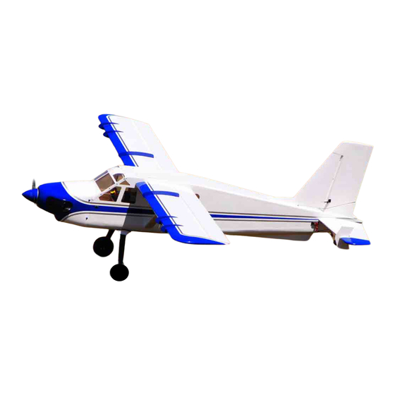
- Page 3 Extreme Flight and Legacy Aviation are excited to announce the release of the long awaited 120" Bushmaster! The brainchild of Cody Wojcik, this design builds on the legacy of the original 84" and 65" versions which have become must have additions to the hangars of RC enthusiasts around the globe. Renowned for its ability to be both a "relaxing but never boring" sport model as well as a fully capable bush style aerobat, the Bushmaster design has won legions of fans who simply want a great flying model with a unique appearance and style. Now Legacy Aviation delivers the next step in this series aimed at the giant scale enthusiast, the 120" Bushmaster! Designed around the Xpwr 60 brushless outrunner and the DA-70 twin cylinder gas engine, the Bushmaster delivers about as much fun as can be had with an RC aircraft with either choice of power plant. We've recently been flying our DA-70 powered version with a 2 into 1 header and single canister muffler setup which delivers quiet consistent power and long flight times. Of course the Xpwr 60 version with a 12S 5000+ mah battery setup provides excellent power and is clean and quiet. Whichever power system you choose, you are certain to have a most fulfilling flying experience! The Bushmaster features a lightweight built up balsa and plywood airframe with strategically placed composite reinforcements to add strength and rigidity. It features a carbon fiber main gear and tailwheel assembly along with carbon fiber wing, stab and rudder mounting tubes and two gorgeous Ultracote (Oracover) color schemes. An expertly painted fiberglass cowl is standard fare along with a pro level hardware package. An optional float kit is also available for water based operations. Ultracote/Oracover Color Codes: White/Blue/Silver scheme: Ultracote HANU870 White, HANU885 Midnight Blue, HANU881 Silver. Oracover 21-010 White, 21-052 Dark Blue, 21-091 Silver. Yellow/Black/Grey scheme: Ultracote HANU872 Bright Yellow, HANU874 Black, HANU882 Light Grey. Oracover 21-033 Cadmium Yellow, 21-071 Black, 21-011 Grey.
- Page 4 Recommended accessories: Desert Aircraft DA-70 gas engine or Xpwr 60cc brushless outrunner MTW TD 110H rear exhaust canister with 60mm drop, 2-into-1 header and coupler kit 24-34 ounce Flowmaster gas tank EF Anodized fuel dot EF Blue fuel line 5 2" EF servo arms (ailerons, flaps, rudder) 2 1.5" EF servo arms (elevators) 1 1" EF servo arm (throttle) 1 1.25" EF light weight servo arm (tailwheel steering) Blazing Star DA-70 mount Blazing Star XXL Standoff set for Xpwr 60 Castle Creations 160HV ESC Falcon 24x9 carbon prop for DA-70 Xoar 24x10 or 24x12 wood or Falcon 26x8 carbon prop for Xpwr 60 Qty. 2 – EF 6 inch 20 AWG servo extension (Flaps) Qty. 3 – EF 24 inch 20 AWG servo extension (Ailerons, throttle) Qty. 3 - EF 36 inch 20 AWG servo extension (Elevators, tailwheel servo) Qty. 1 – EF 48 inch 20 AWG servo extension (Rudder) 2 sets EF MPX Multi-wire servo plug (2 wire version) EF Servo Wire Safety Clips 4" EF Carbon Fiber spinner 7 high torque metal gear servos for control surfaces (MKS 1220, MKS 777 A+ or equivalent) 1 high speed servo for throttle (MKS 1250) 1 metal gear mini servo for tailwheel steering (Hitec 5245, 7245)
- Page 5 Let’s begin! 1. Locate the 2 wing panels as well as the G10 aileron and flap control horns. Use sandpaper to scuff the portion of the control horn that will be glued into the surface. For a more finished look you may wish to paint your control horns before installation. Do not paint the portion of the control horn that will glue into the control surface. 2. Using a soldering iron or a sharp hobby knife, remove the covering from the slots for the aileron and flap horns. Place the control horns into the baseplate. Dry fit the horns into their respective slots and trim any debris from the slot until the control horn seats properly against the control surface. Sand away any portion of the baseplate that may extend beyond the edge of the bevel. Once satisfied with fit remove the control horns and use your hobby knife to remove the covering that is under the baseplate for best glue adhesion to the surface.
- Page 6 3. Apply a generous portion of 30-minute epoxy to the aileron and flap control horn slots and to the scuffed area of the control horns. It may be helpful to use a zip tie to push the epoxy into the slots. 4. Assemble the control horns and ball links as shown and install the control horns into their respective slots. Wipe away any excess epoxy with a paper towel or cloth soaked with denatured alcohol. 5. In these next steps we will install the hinges. Please take a few moments to familiarize yourself with this process if you have not installed hinge points before. There are several ways to do this and several adhesives you can use. We will describe the way that we do it, as this method has proven itself over many years of model building. If you are new to this type of hinging process, then I recommend that you install a single hinge first just to acquaint yourself with this method Before starting you will need to gather a few items to aid you as you proceed. A. 30 Minute Epoxy B. A short length of pushrod or small dowel. C. A roll of paper towels D. Denatured alcohol or Acetone E. Hobby Knife F. Teflon lubricant...
- Page 7 Locate a wing panel and separate the control surfaces from the main wing and remove the hinges. Mix up a generous batch of epoxy and use a piece of pushrod or dowel to apply the epoxy to the hinge hole. 8. Apply epoxy to the barbed section of the hinge on one side and insert it into the hole until the center of the hinge is centered on the hinge line. Using a paper towel soaked with acetone or denatured alcohol wipe away any epoxy that has been squeezed out of the hole.
- Page 8 9. Make sure the hinge can move freely and that the pin is aligned properly before the epoxy sets! When you are satisfied with the results set the surface aside so that the epoxy will pool around the rear of the hinge. When you are comfortable with this process you should be able to do one side of a surface per batch of epoxy. Repeat the process to attach the surfaces to each wing. There should be as little gap as possible while still allowing maximum movement of the control surface. 10. As a final step before setting the wing aside to dry, do a final cleaning of the hinge knuckles with a paper towel soaked with denatured alcohol or acetone to remove any epoxy residue. If you find any of the hinges are stiff after drying, apply a drop of acetone to each hinge with a Q-tip and move the surface back and forth several times to loosen it up. As a final step I typically apply a couple drops of Teflon lubricant to each hinge. This is available at most home improvement and hardware stores. 11. You will need to attach a 24 inch servo extension to your aileron servo to reach the wing root. The flap servo wire will require a 6 inch extension. Secure the extensions to the servo leads with heat shrink tubing or a servo wire safety clip .
- Page 9 12. Use the manufacturer supplied mounting hardware to install the wing servos with the output shaft toward the TRAILING EDGE of the wing. Electronically center the servo and install 2 inch servo arms onto the servo spline. The servo arms should be parallel to the hinge line when centered. It is very important that you use the same length servo arms for both flap and aileron servos . 13. For ease of field assembly we highly recommend using 2 sets of the Extreme Flight MPX Multi-wire servo plugs. Attach these to the servo extensions protruding from the wing for a fast and easy single plug solution to wing servo connections. Be sure to secure the MPX plug lead so that it cannot flop around inside of the wing, possibly causing the plug to pull out of the receiving socket.
- Page 10 14. Use the supplied ball links, turnbuckle pushrods, 3mm bolts, washers and nuts to assemble the aileron and flap linkages and secure to the servo arm and control horns as illustrated in the following photo. Both the aileron and flap linkage are assembled the same way. 15. Locate the wing fences and trial fit onto the wing. Some sanding may be required for best fit. We recommend gluing the fences in place with epoxy. Use tape or clamps to hold the fences in place while the epoxy cures making sure they are perpendicular to the surface of the wing. Two strips of tape placed parallel to the fences will keep excess epoxy from getting on the wing surface.
- Page 12 16. Locate the landing gear components and the associated fastener package form the hardware kit. Secure the carbon fiber landing gear to the fuselage with the provided 4mm socket head cap bolts, washers and lock nuts. 17. Apply a bead of Goop adhesive to the carbon gear and slide the landing gear fairing into position against the bottom of the fuselage. Secure with tape until the adhesive dries.
- Page 13 18. Attach the axles to the carbon gear with the supplied washer and locknut.
- Page 14 19. File a flat spot on the axles for the wheel collar set screws to seat against. Secure the wheel into position with a collar placed on each side. Be sure to use Loctite on all fasteners!
- Page 15 20. Assemble the tailwheel as shown. It is highly recommended that you flie a flat spot at the location that each set screw will seat and again, apply blue threadlock compound to all screws. 21. Install the tailwheel assembly onto the bottom rear of the fuselage with the provided 3mm bolts included in the hardware package. This step will allow us to turn the fuselage over and place it on its "feet" which will allow a better position to install the engine.
- Page 16 22. Flip the fuselage and lets install our power plant of choice. Drill 4 1/4" holes at the designated location for your motor/engine. 23. If using the Xpwr 60 it is highly recommend that you use the Blazing Star XXL Standoff Set to achieve proper spacing with minimal hassle. If using the DA-70 the Blazing Star mount makes proper engine positioning a breeze!
- Page 17 24. In the previous photo you can also clearly see the installation of the 2-into-1 header/canister setup and the throttle servo installation. Here are a few more pics of the engine setup including the ignition mounting location and the cooling cutouts on the bottom of the cowl.
- Page 18 25. The Bushmaster cowl, because it lacks any air inlets, requires some creative cooling methods to keep our power system running properly. In the previous photo you can see the cutouts we made in addition to the air dam we installed to pull air over the engine and out of the cowl. This was fabricated from a piece of aluminum flashing purchased from a local home improvement store. Proper ventilation is a must!!!!
- Page 19 26. In addition to opening up the bottom of the cowl we also made sure the dummy exhaust stacks contributed to pulling air over the cylinders and removing it from the cowl by opening the cowl and exhaust stacks before gluing in place. Remove as much paint as possible from the gluing surface as possible and glue in place with 30 minute epoxy. 27. Before final installation of the cowl and depending on your choice of power system install either your gas tank on the tank/battery tray with plumbing or the ESC.
- Page 20 28. Install the lower cowl half, with the 4 3mm bolts provided in the hardware package, followed by the top piece of the cowl with 4 more 3mm bolts. In this photo we have added the EF anodized washers for a touch of bling. 29. Locate the stab/elevator set along with the elevator control horns. Using the same method as the ailerons, hinge both stab halves and install the control horns in the location shown.
- Page 22 30. Install the elevator fences with the provided 3mm bolts inserted through the fence and into the pre-installed blind nuts in the stab. 31. Slide the carbon fiber stab tube into the sleeve in the fuselage rear, then slide both stabs onto the tube and secure with 2 3mm bolts and washers inserted through the tabs at the stab root and into the blind nuts pre-installed in the fuselage. Be sure to use thread lock on all bolts. 32. Install your elevator servos in the proved location and assemble the linkage as shown in the following pictures.
- Page 23 33. Place the rudder fairing block into position and trace around it with a fine tipped felt marker. Use a sharp hobby knife to remove the covering as shown for a wood to wood bond and glue in place with medium CA or epoxy. Be sure to check alignment with rudder before gluing!
- Page 24 34. Using the same method as with the ailerons and elevators, glue the rudder hinges and rudder control horns in place with 30 minute epoxy. 35. Install the rudder servo in the designated location inside the vertical fin with the output spline oriented toward the rear of the model and assemble the linkage as shown.
- Page 25 36. Slide the carbon fiber rudder mounting tube into the receptacle in the fuselage. Slide the rudder into position and secure with 2 3mm bolts and washers.
- Page 26 37. Install the tailwheel steering servo into its designated location and assemble the linkage as shown. 38. If you are planning to install the float kit and fly from water install the keel on the bottom of the fuselage. Glue in place with epoxy making sure it is perpendicular to the bottom of the fuselage. Use tape to keep it properly positioned until the glue dries.
- Page 27 39. Insert the carbon fiber main wing tube into the sleeve in the fuselage. Slide the wings into position taking care to insert the servo extensions into the fuselage. Secure the wings by inserting the nylon wing bolts into the holes in the fuselage and threading them into the blind nut in the wing root. 40. Attach the wing struts using the supplied 3mm cap head bolts inserted through the holes in each end of the struts and into the attachment points in the wing and fuselage. You may find it easiest to start with the wing attachment first. Don't fully tighten until both bolts are inserted into the pre-installed blind nuts. This concludes the assembly process for the 120" Turbo Bushmaster. Preparing for flight! With the wing and struts attached, place your batteries in the model and pick up the Bushmaster by the wing tube. Shift the batteries until the plane balances on the tube, then secure the batteries with velcro. This is a safe location to begin test flying. It is recommend you first fly the model in standard configuration to get used to its flight characteristics before beginning to experiment with flaps. When deploying flaps you will need to add an elevator mix that compensates for the flaps and provides a few degrees of down elevator. Thanks so much for your business and we hope you enjoy flying your Turbo Bushmaster as much as we have!
Need help?
Do you have a question about the Turbo Bushmaster and is the answer not in the manual?
Questions and answers