Advertisement
Quick Links
Advertisement

Related Manuals for Extreme Flight EDGE 540T EXP


Summary of Contents for Extreme Flight EDGE 540T EXP
- Page 1 EDGE 540T Electric ARF 1 ...
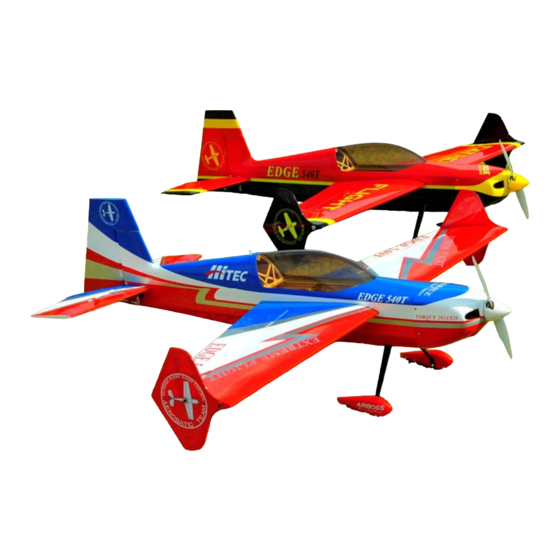
- Page 2 If repairs become necessary, the Ultracote colors used on the Edge 540T EXP are as follows: Red/black color scheme: True Red, Bright Yellow, Black Red/white/blue color scheme: True Red, White, Deep Blue, Silver 2 ...
- Page 3 Your flying experience will be greatly enhanced by doing this. Please note The assembly of the Edge 540T EXP is almost identical to the assembly process of the previously released Extra 300 EXP. Most photos will show the Extra component assembly. Only assembly steps which differ will show the Edge.
- Page 4 LiPos available from www.hobbycity.com in both 2200 mah and 2350 mah sizes. -APC 12x6 E prop (NOT the slow fly version!). -52mm Extreme Flight spinner. -2 18"-24" extensions for the 2 rear servos and 2 6"-8" extensions to go between the receiver and the aileron servo leads.
- Page 5 Let's begin! 1. So that we don't have to wait for the 30 minute epoxy to dry in a later step, let's go ahead and prepare the 4 carbon fiber pushrods and ball links for later use. Locate the 4 carbon fiber pushrods and 4 micro ball links in the hardware package.
- Page 6 3. Use a paper towel to wipe away most of the excess epoxy, leaving a small fillet between the carbon pushrod and ball link. Position the pushrods vertically while they cure as illustrated so the fillet remains in position. DO NOT use CA for this bond! 4.
- Page 7 5. Scuff the portion of the control horn that will be glued into the aileron with sandpaper. 6. Use a glue tip on your bottle of medium CA and apply glue to the slot as well as to both sides of the control horn. Insert the control horn into the slot and make sure it seats properly against the surface of the aileron.
- Page 8 7. Remove the covering from the aileron servo location and make sure the hinges are centered in their slots. 8 ...
- Page 9 8. Slide the aileron into position on the hinges and secure with several drops of fresh thin CA. This process is much easier and more effective if a fine glue tip is used. Make sure to deflect the surface as pictured while applying the 9.
- Page 10 within the hole. Place the retaining nut on the threaded portion of the connector shaft and screw down until tight, then back off the nut just enough to allow the connector to turn freely. Place a single drop of CA on the end of the threaded shaft to prevent the nut from coming off.
- Page 11 11. Two of the carbon pushrod/ball link assemblies are the same size. These are the aileron pushrods. In addition locate 2 silver 2 mm screws, washers and nuts from the hardware package. Secure the ball link side of the pushrod to the aileron control horn on the side of the horn that will be closest to the fuselage by inserting a 2mm bolt into a washer, then through the hole in the brass ball and finally through the hole in the G10 control horn.
- Page 12 12. Secure the carbon pushrod to the EZ connector with the provided set screw. Take care not to over tighten the set screw and crush the carbon rod. Once you feel the set screw engage the carbon pushrod another 3/4 to 1 turn will supply adequate pressure to retain the pushrod.
- Page 13 Here is a photo of the completed installation. Repeat this process for the other wing half. 13. Locate the fuselage, one piece carbon fiber landing gear, 2 silver 3mm machine screws and 2 washers. Secure the landing gear to the fuselage by inserting a 3mm screw into a washer, through the carbon fiber gear and into the pre-installed blind nut in the fuselage.
- Page 14 14. Locate the 2 axles, 2 locking nuts, 2 wheels, 2 wheel collars and 2 wheel pants from the hardware package. Place the wheel onto the axle and secure with a wheel collar. Place the threaded portion of the axle through the hole in the carbon gear and screw the lock nut onto the axle, but do not tighten completely.
- Page 15 15 ...
- Page 16 15. Locate the horizontal stabilizer/elevator assembly and slide the elevator off of the hinges. Insert the stabilizer into its slot and the carbon fiber wing tube into the fiberglass sleeve. Use a ruler to insure that the stabilizer is centered in its slot and compare the stabilizer to the wing tube to make sure it is properly aligned.
- Page 17 17. Slide the elevator onto the hinges in the stabilizer and secure with thin CA. Again a fresh bottle of CA and a fine glue tip work best here 18. Remove the covering over the slot in the lower right side of the rudder where the rudder control horn will be installed.
- Page 18 19. Using the same process as with the ailerons and elevator, slide the rudder onto the hinges and secure to the vertical stabilizer with thin CA. 20. Locate the carbon fiber tailwheel assembly in the hardware package. Secure the tailwheel bracket to the bottom rear of the fuselage with the provided wood screws.
- Page 19 22. Place the tailwheel wire in the proper position, aligned with the rudder and lock into place with the 2 set screws. 23. Use the hardware provided with the servos to install the rudder and elevator servos in their respective location in the rear of the aircraft. From the pilot's perspective the rudder servo mounts on the right side of the fuselage and the elevator servo mounts on the left side.
- Page 20 25. Mount the motor using the supplied 3mm black socket head cap bolts which are threaded into the blind nuts which are pre-installed in the motor mount plate. Be sure to put a drop of blue Loctite onto each bolt to prevent them from backing out.
- Page 21 Roll the tape back and slide the cowl into position. Install an Extreme Flight 52mm spinner onto the motor shaft for reference and once satisfied with the cowl position roll the tape back into place and secure the cowl.
- Page 22 28. There is a laser cut opening in the bottom of the fuselage under the rear of the canopy. Use a sharp hobby knife to remove the covering from this location to allow cooling air to exit the fuselage. 22 ...
- Page 23 29. Use nylon cable ties or Velcro to secure the ESC to the bottom of the motor box. There is an opening in the cowl just in front of this location to allow cooling air to enter and be directed over the ESC. 30.
- Page 24 31. If using the included Side Force Generators now is the time to mount them. Each SFG mounts using 2 3mm bolts and 2 clear plastic washers. There are 2 laser cut holes in each SFG which correspond with 2 laser cut holes in the tip of each wing.
- Page 25 Set-up and flying tips The CG range for the Edge starts at 3.75 inches back from the leading edge of the wing and extends back to 4.25 inches, measured at the wing root. There is plenty of room on the battery tray to move your battery to achieve this CG location.
- Page 26 3D flight will allow you to experience the best attributes of the Edge 540T EXP or any aircraft for that matter. The included elevator servo arm will allow for close to 80 degrees of throw! While...
- Page 27 Again, these are my preferences, adjust to suit your flying style and preferred feel. The Edge 540T EXP is capable of performing the full range of known 3D and precision maneuvers. It is also capable of performing all kinds of crazy aggressive maneuvers that have yet to be named.
- Page 28 We have had a blast during the development and testing stages of this aircraft and I sincerely hope the Edge 540T EXP provides you with as much joy and excitement as it has for me. See ya at the flying field! 28 ...
Need help?
Do you have a question about the EDGE 540T EXP and is the answer not in the manual?
Questions and answers