Advertisement
Quick Links
Advertisement

Subscribe to Our Youtube Channel
Related Manuals for Extreme Flight Turbo Raven 69"


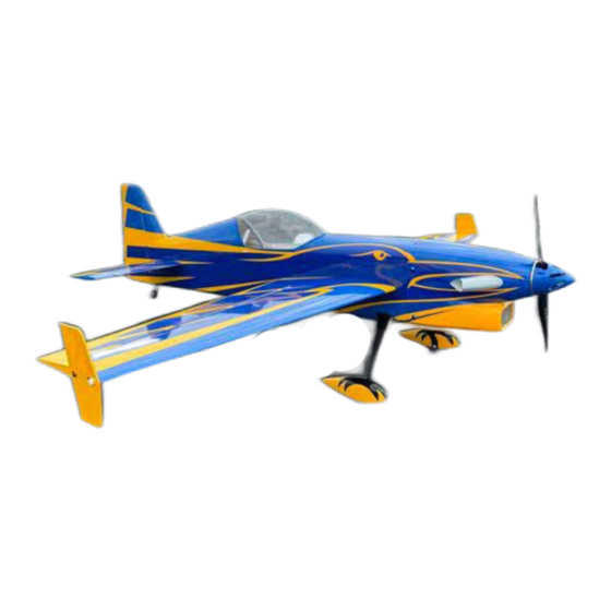
Summary of Contents for Extreme Flight Turbo Raven 69"
- Page 1 TurboRaven 69” 69” Build Guide...
- Page 2 Extreme Flight RC guarantees this kit to be free of defects in materials and workmanship for a period of 30 DAYS from the date of purchase. All warranty claims must be accompanied by the original dated receipt. This warranty is extended to the original purchaser of the aircraft kit only.
- Page 3 Learning to remove wrinkles from covering is a necessary skill to maintain your wood aircraft. Your Extreme Flight produced aircraft is covered in Ultracote covering material (US market name), also called Oracover in global markets. If you need replacement covering to repair damage, Ultracote/Oracover is widely available from retail hobby suppliers.
- Page 4 Locate the control horns for your Raven. The assembly has two parts, the horn itself, and the trim plate. Do not discard the trim plate, it holds the horn in proper position during installation. The Raven uses a pull-pull rudder assembly with two horns, one on each side of the rudder. Begin by using 120-180 grit sandpaper or emery board to scuff the horns where they insert into the surfaces as shown.
- Page 5 Install your aileron servos with wire extensions; we chose to pre-drill the servo screw locations with a 1/16” drill bit as shown. Assemble the aileron pushrods as shown, we chuck the pushrod into a cordless drill to assist with screwing the nylon ball links on. Install the servo arm and pushrod as shown, using the supplied hardware with washers and locking nuts.
- Page 6 Install the landing gear into the fuselage with included bolts, washers and blue loctite thread locker. Note that the Raven landing gear sweeps slightly forward when installed correctly. Using Gorilla Clear Bond, Goop, or another rubberized adhesive, install the cover plate for the gear. Locate the gear fairings, and test fit to find the best fit to the fuselage.
- Page 7 Attach the axles to the landing gear with washers and locking nuts as shown. Install the wheel and wheel collar, using loctite on the collar set screw. Note that the axle has a flat spot for the collar set screw ma- chined in.
- Page 8 Remove the trim block from the stabilizer slot in the fuselage. The horizonal stabilizer and ele- vators slide into the slot. Make sure the stab is oriented correctly top-to-bottom, and test fit the stab into the slot. Push it all the way forward into the slot. Check the fit of the stab, the motion of the elevators, and test fit the trim block back in place to make sure everything has proper clearance for full elevator throw.
- Page 9 Install the rudder with the wire hinge as shown. Locate the tailwheel, use the two wood screws to install it onto the fuselage as shown. Use the third wood screw to connect the tiller to the bottom of the rudder. NOTE - the tiller screw should not be fully tight and should be free to slide a bit within the slot to ensure smooth rudder motion.
- Page 10 Assemble and install the elevator pushrod as you did for the ailerons. Install the elevator servo with its wire extension. Install the servo arm and hardware as shown.
- Page 11 Mount your rudder servo as shown, and feed the pull-pull cables into the fuselage as shown. Feed the cables forward to the servo, crossing them once to make an “X” shape. Screw the ball links onto the metal cable ends. Attach the cable end assemblies onto the rudder servo arms as shown. The photo sequence shows how to assemble cables with crimp tubes onto the cable ends, pulling them tight and crimping the crimp tubes with pliers.
- Page 12 Center the rudder and arm and connect the rear ends of the cables as you did the front. Try to pull as much slack out of the cables as possible. Crimps the tubes and add one drop of thin CA to each tube to finish. After the cables are assembled, take up any remaining slack by screwing the threaded cable ends into the ball links.
- Page 13 Here we show the installation of the recommended T-Motor AM600 power combo with AM116 ESC. Apply shims to the mount, and the washers included in the motor package behind the prop adaptor as needed to achieve proper spinner-to-cowl spacing (2-3mm recommended). Use Clear Bond or other rubberized glue to attach the exhaust stacks to the cowl as shown.
- Page 14 Install the clear plastic chin scoop deflector into the cowl with medium CA to deflect air toward the brushless motor. Install the cowl, spinner and prop. NOTE: Never power up your aircraft with the prop attached unless it is pointed in a safe direction and properly re- strained.
- Page 15 Install the clear wingtip spacers, SFGs and (if desired) extension wingtips. The Raven feels different in each configuration of SFG with tip, SFG without tip, and tip only, so try them all. TEMPORARY NOTE: The first few shipments of 69” Raven v2 have a mislocated hole in the clear plastic wingtip, this will be corrected on later shipments, you may need to drill the rear hole as shown to correct.
- Page 16 Center of Gravity : Our preferred C of G for maiden flight is 1/2” (12mm) behind the wing tube. Control settings: Elevator: Low Rate 8-10 deg. 15-20% expo 3D Rate 45-60 deg. 60-65% expo Aileron: Low Rate 15-20 deg. 40-45% expo High Rate 38-40 deg.
Need help?
Do you have a question about the Turbo Raven 69" and is the answer not in the manual?
Questions and answers