Advertisement
Quick Links
Advertisement

Related Manuals for Extreme Flight 104" MXS-EXP ARF


Summary of Contents for Extreme Flight 104" MXS-EXP ARF
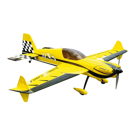
- Page 1 104" MXS-EXP ARF Assembly Manual Copyright 2016 Extreme Flight RC...
- Page 2 If you are not willing to accept ALL liability for the use of this product, please return it to the place of purchase immediately. Extreme Flight RC, Ltd. guarantees this kit to be free of defects in materials and workmanship for a period of 30 DAYS from the date of purchase. All warranty claims must be accompanied by the original dated receipt.
- Page 3 We are very proud of the end result of our labor and wish you great success with the assembly and flying of your Extreme Flight RC 104 inch MXS!
- Page 4 1 x standard size servo for the throttle. 4 x Extreme Flight 1.5” single aluminum Servo Arms for the ailerons 2 x Extreme Flight 2” single aluminum arms for the elevators (3 if using a tail mounted rudder servo and 4 for double tail rudders servos) 1 x Extreme Flight 4”...
- Page 5 Your flying experience will be greatly enhanced once your plane is properly dialed in. 7. Extreme Flight now has their own Vimeo channel. There are many assembly videos providing extreme detail on certain aspects of the assembly of this very model produced by Extreme Flight team pilot Jeff Williams.
-
Page 6: Let's Begin
Let's Begin: 1. Locate the wing panels/ailerons and horizontal stabilizers/elevators and associated hardware bags. We will begin by hinging all of these at one time. I suggest you scuff/rough the surface of the hinges, they are slick from the manufacturing process and the glue will adhere better to a non-slick surface. Using 100-150 grit sandpaper works well to do this, be sure you don't sand the barbs off the hinge, you just want a little scuffing on the hinge, do not sand at the pivot. - Page 7 Figure 1 2. Install the control horns for the ailerons, be sure to note that the outer horns are the ones with the upper hole and the inner horns have it located nearer the middle (Figure 2). Once you have them inserted into the holes I advise you temporarily install the 3mm bolt and ball link, this is only to keep the control horns spaced properly and evenly, remove them once the glue is dry.
- Page 8 Then hook it to your servo arm in the same manner and use blue thread lock. See Figures 3 & 4. Figure 2 Scuff this portion only Figure 3...
- Page 9 Figure 4 3. Install the elevator servos, orient the output shaft toward the hinge line of the horizontal stabilizer. It will be easier to install the servo arms after mounting the servo. Make all hookups for the pushrods/ball links as we did in the previous step.
- Page 10 4. Hinge the rudder and install the control horns using the same technique(s) as the wing. Then you can mate the rudder to the vertical stabilizer. See Figures 6 & 7. Figure 6 5. Mount your rudder servo in the rear (Figure7) or the center mount location just aft of the wing tube inside the fuselage which will require a pull pull setup (hardware is included).
- Page 11 Figure 7 6.Next we will install the main landing gear, axles, tires, wheel pants and wheel cuffs. Now is the time to decide whether you are going to install the wheel cuffs. If you do go with the cuffs then slide the black tubing and use either Welders adhesive, Amazing goop or CA will work too.
- Page 12 tightening the nylon insert nut to the axle, be careful to not overtighten. If you ground a flat spot I find it best to position that facing the bottom so future wheel collar retightening is more accessible. Now install one wheel collar, the tire then the other wheel collar but don’t tighten.
- Page 13 Figure 10...
- Page 14 Figure 11 7. Locate your tailwheel package and have the fuselage supported to aid in this installation step. Begin by drilling a 1/8” hole centered in the bottom of the rudder approximately 3” aft of the rudder hinge line. Then insert the white ball link that will support the tiller arm and use 30 minute epoxy (suggest roughening the ball link for better adhesion).
- Page 15 Tailweel bracket Tiller arm Nylon insert nut Tiller housing Tailwheel wire Figure 13...
- Page 16 8. Locate your motor and we will begin the mounting process, 1.125” standoffs will work perfectly for the DA120. If you are using a different motor then plan on needing 7.25" from the firewall to the front of the cowling, you may want toadd 1/8"...
- Page 17 Figure 15 9. Install the throttle servo, depending on your choice of setup and engine brand you may have to drill a hole/slot thru the firewall to access the throttle arm on the carburetor from your servo. With the DA120 motor we mounted the servo upright in the engine box and cut a small slot in the firewall for the throttle pushrod.
- Page 18 Figure 16 Slot thru firewall Pushrod Easy swivel connector Round nut Figure 17 Slot thru firewall Ball link Washer...
- Page 19 10. Trial fit the engine cowling to determine fit and any cutting of clearance holes. With stock mufflers you will have to cut the cowling, using headers/pipes/canister mufflers you will likely not need to cut the cowling for clearance. Determine any cooling holes and cut accordingly. There is no way I could cover every scenario, so I have only included pictures of my cowling with stock mufflers.
- Page 20 Figure 19 Small hole for access to high and low needles on carburetor. Typical slot cuts for stock mufflers. 11. The basic assembly is complete, now figure where you want to install the switches (there are precut holes just aft of the cowling). Install your tank in the tray just in front of the wing tube and secure with velcro/zip ties and put foam under tank.
- Page 21 12. Install your batteries in the rudder tray, now determine your center of gravity. The desired range is: Forward limit CG - front of wing tube Most desirable CG – Midpoint of wingtube to trailing edge of wing tube Aft limit CG –up to .5" behind the trailing edge of the wing tube Move your batteries to achieve desired CG in this range.
- Page 22 If you fly like this, you must preflight your aircraft and perform normal inspections and maintenance. Many of our Team Extreme Flight members fly this style and do this as part of their normal routine of maintaining a safe and proper flying aircraft.
- Page 23 Earlier we provided a recommended setup, this is how Jeff Williams has setup his aircraft and would likely be a more popular setup for most flyers who like to run rates. However those that run only one rate might find Jase Dussia’s setup below helpful for this exact aircraft, these numbers were taken from his transmitter: Jase Dussia’s Heavy metal warbird scheme 104”MXS:...
- Page 24 Insert the bare end of the cable into the slot in the rear of the fuselage and feed it forward into the canopy area. Make the same type of linkage as done previously. Electronically center the servo and secure the linkage at both ends with a 3mm bolt and nylon insert lock nut as we did on the other surfaces.
Need help?
Do you have a question about the 104" MXS-EXP ARF and is the answer not in the manual?
Questions and answers