
Subscribe to Our Youtube Channel
Related Manuals for Delta IMA-1000 Series


Summary of Contents for Delta IMA-1000 Series
- Page 1 IMA 1000 Watts Power Supply Series for medical and industrial applications Application note...
-
Page 2: Table Of Contents
Features NOTE This product is only for installation by professional electricians within other equipment and must not be operated as a standalone product. Table of Contents Features ● Safety approval for Medical (IEC 60601-1-2), Industrial (IEC 62368) and IT 1. Features ●... -
Page 3: Overview
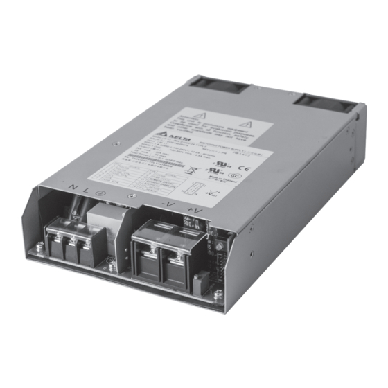
Overview Overview Right side surface Top surface Airflow Left side surface Base surface Fig. 1: Components of the IMA-x1000 AC/DC input terminal block (J1) DC output terminal block (J2) Output voltage adjustment potentiometer Signal connector and Auxiliary DC Output (J3) Green status LED Fans IMA-x1000-xx-Series_Application_Note_V4.0_XX_EN_2019-08-19... -
Page 4: Ac/Dc Input Terminal Block (J1)
Overview AC/DC Input terminal block (J1) Signal port and Auxiliary DC Output (J3) J1 is the input connector, a standard screw type 3-pin con- nector with clamp washer and a terminal centres pitch dis- tance of 9.5 mm (0.37 in). Fig. -
Page 5: Main Dc Output Terminal Block (J2)
Overview Main DC Output terminal block (J2) Output voltage adjustment potentiom- eter J2 is the output connector, a standard screw type 2-pin connector with clamp washer and a terminal centres pitch The Output voltage adjustment potentiometer is for out- distance of 16 mm (0.63 in). put voltage adjustment within the range of specifications. -
Page 6: Electrical Functions
Electrical functions Electrical functions No-load operation A no-load condition causes no damage, hazardous condi- tion or reduction in performance. Input requirements The AC input voltage and the DC input voltage must be in Fan Speed Control the defined voltage ranges (see data sheet). Otherwise, the power supply may not work properly or even fail. -
Page 7: Output Over Current Protection (Ocp)
50 °C (122 °F). If you need to adjust the settings for the OCP function, please contact Delta. At ambient temperatures above 50 °C (122 °F), the output power at the Main DC Output is linearly derated from 100% at 50 °C (122 °F) to 50% at 70 °C (158 °F). -
Page 8: Remote On/Off
Electrical functions 3.11 Remote ON/OFF An internal pull up resistor with 1 kΩ is connected to +5VSB standby power, see Fig. 11, p. 8. If an input voltage has been connected to the Power Supply Power Supply Unit Unit, the Remote ON/OFF function is used to turn the DC Main Output on and off. -
Page 9: Power Good
Electrical functions 3.12 Power Good 3.13 Output voltage ripple and noise When the input voltage fails, the Power Good function pro- Ripple and noise are measured at 20 MHz by using a vides a time delay before the Main DC Output is switched twisted pair of load wires terminated with a 0.1 µF film off. -
Page 10: 3.15.1 Redundant Operation
If you need more than 2 units operating redun- current sharing between the Power Supply Units. For par- dantly, please contact Delta. allel operation, the CS buses of all Power Supply Units of An Or-ing circuit is built-in to prevent that the redundant sys- the redundant system have to be connected. - Page 11 Electrical functions 3.16.1 I C slave address To identify the Power Supply Unit in a redundant system, an I C slave address can be applied to each Power Supply Unit. The address can be set as a voltage on J3 Pin 12 (ADDRESS).
-
Page 12: Installing The Ima-X1000
To ensure sufficient fan cooling while the device is in opera- tion, the clearance should be as large as possible on both General safety instructions the fan side and the terminal block side surface. In Delta qualification, simulation wall was placed and kept minimum WARNING 20 mm from fan side surface, see Fig. - Page 13 Installing the IMA-x1000 Fig. 18: Electromagnetic compatibility IMA-x1000-xx-Series_Application_Note_V4.0_XX_EN_2019-08-19...
-
Page 14: Mounting The Power Supply Unit
Installing the IMA-x1000 Mounting the Power Supply Unit Use M3 screws with the appropriate length (see Fig. 19, p. 14) through the base mounting holes. This is neces- sary to ensure a safety distance between the screw and internal components. Recommended mounting tightening torque is 0.6 Nm (5.3 lb-in). - Page 15 Installing the IMA-x1000 Mounting orientations Fan side Connector side ≥20 mm (≥0.79 in) Fig. 20: Standard mounting orientation Connector side Bottom Bottom Fan side Fig. 21: Vertical mounting Fig. 22: Mounting on the left side Fig. 23: Mounting on the right side Bottom view Side view Mounting holes...
- Page 16 Installing the IMA-x1000 Dimensional drawings +1.0 +0.04 209.5 mm (8.25 in -1.0 -0.04 PIN2 PIN1 AIRFLOW 145.0 mm (5.71 in) 30.5 mm (1.2 in) M3 screw hole (2x) both sides 160.0 mm (6.30 in) 15.5 mm (0.61 in) M3 screw hole (4x) bottom side Fig.
-
Page 17: Disposal
Disposal Disposal Do not dispose of electrical appliances as unsorted munici- pal waste, use separate collection facilities instead . Contact your local authorities for information regarding the collection systems available. If electrical appliances are disposed of in landfills or dumps, hazardous substances can leak into the groundwater and get into the food chain, damaging your health and well-being. -
Page 18: Appendix
Appendix Appendix Curves IMA-x1000 IMA-x1000 Tested at 90 Vac input Output power [%] Output power [%] [°C] [°F] Ambient temperature Input voltage [Vac] standard mounting orientation all other mounting orientations Fig. 26: Output power versus input voltage Fig. 27: Output power versus ambient temperature IMA-x1000-12 IMA-x1000-24 Output current [A]... - Page 19 Appendix IMA-x1000-12 Efficiency [%] Output power [%] 230 Vac 115 Vac Fig. 31: Typical efficiency curves 12 V IMA-x1000-48 Efficiency [%] Output power [%] 230 Vac 115 Vac Fig. 32: Typical efficiency curves 48 V IMA-x1000-24 Efficiency [%] Output power [%] 230 Vac 115 Vac Fig.
-
Page 20: Pmbus
PMBus™ stan- dard is supported, thus user can monitor and control the Power Supply Unit via I2C communication digitally. Please contact your Delta sales partner for details. Fig. 34: Graphical User Interface of the PMBus™ IMA-x1000-xx-Series_Application_Note_V4.0_XX_EN_2019-08-19... -
Page 21: Pmbus™ Command Map
PMBus™ PMBus™ Command Map The following sets of standard commands are supported as per the standard PMBus™ protocol specification. While reading data using any of the standard PMBus™ com- mands, the power supply should always send the LSB first followed by MSB with bit order of the bytes from 7 to 0. (big- ending). - Page 22 PMBus™ Command Command Name Page Transaction Type Data Number Instruction Code Format of data Writing data Reading data bytes (12V) (5VSB) STATUS_VOUT √ √ Read Byte return one data byte with contents: Output Overvoltage Fault, Warning, Undervoltage Warning, Fault TON_ MAX_FAULT’TOFF_ MAX_WARNING, VOUT Tracking Error...
- Page 23 PMBus™ Command Command Name Page Transaction Type Data Number Instruction Code Format of data Writing data Reading data bytes (12V) (5VSB) READ_VOUT √ √ Read Word Linear return the actual, mea- sured (not commanded) output voltage in the same format as set by the VOUT_MODE command READ_IOUT √...
- Page 24 Sales Contact Europe Delta Energy Systems (Germany) GmbH Tscheulinstrasse 21 79331 Teningen Germany deu.sales@deltaww.com www.deltaenergysystems.com Delta Electronics (Americas) 46101 Fremont Blvd. Fremont, CA 94538 na.sales@deltaww.com www.deltaenergysystems.com Other regions Delta Energy Systems (Germany) GmbH Tscheulinstrasse 21 79331 Teningen Germany im.sales@deltaww.com www.deltaenergysystems.com IMA-x1000-xx-Series_Application_Note_V4.0_XX_EN_2019-08-19...
Need help?
Do you have a question about the IMA-1000 Series and is the answer not in the manual?
Questions and answers