Table of Contents
Advertisement
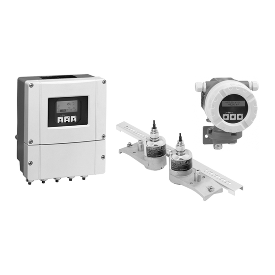
Technical Information
Proline Prosonic Flow
90U, 90W, 91W, 93C, 93U, 93W
Ultrasonic Flow Measuring System
Flowrate measurement for standard applications
with drinking water, wastewater and process water
Application
The sensors are perfectly suited for bidirectional
measurement of pure or slightly contaminated liquids,
regardless of the pressure, temperature, conductivity
and viscosity.
• Applicable for all homogeneous fluids in acoustically
transmissive pipes, even with lining
• For water/wastewater applications
• Ideal for retrofitting
• Installation without process interruption
Approvals for hazardous area:
• ATEX, FM, CSA
Approvals in the food industry/hygiene sector:
• Drinking water approval for Prosonic Flow C
Connection to process control system:
• HART, PROFIBUS PA, FOUNDATION Fieldbus
TI057D/06/en/04.06
71026244
Your benefits
Prosonic Flow, the flexible and cost-effective flow
measuring system, available as a clamp-on, insertion or
inline unit, offers you a tailor-made solution.
The Proline transmitter concept comprises:
• Modular device and operating concept resulting in a
higher degree of efficiency
• Diagnostic ability and data back-up for increased
process quality
The tried-and-tested Prosonic Flow sensors offer:
• Easy and safe installation and commissioning
guarantee precise measurement
• Insensitivity to vibrations
• No pressure loss
• Optionally available as dual-path version for short
inlet runs
• Prosonic Flow C with guaranteed and attestable
accuracy
Advertisement
Table of Contents

Related Manuals for Endress+Hauser Proline Prosonic Flow 90U


Summary of Contents for Endress+Hauser Proline Prosonic Flow 90U
-
Page 1: Technical Information
Technical Information Proline Prosonic Flow 90U, 90W, 91W, 93C, 93U, 93W Ultrasonic Flow Measuring System Flowrate measurement for standard applications with drinking water, wastewater and process water Application Your benefits The sensors are perfectly suited for bidirectional Prosonic Flow, the flexible and cost-effective flow measurement of pure or slightly contaminated liquids, measuring system, available as a clamp-on, insertion or regardless of the pressure, temperature, conductivity... -
Page 2: Table Of Contents
Proline Prosonic Flow 90U, 90W, 91W, 93C, 93U, 93W Table of contents Function and system design..... 3 Degree of protection ....... . . 31 Shock and vibration resistance . -
Page 3: Function And System Design
Proline Prosonic Flow 90U, 90W, 91W, 93C, 93U, 93W Function and system design Measuring principle Prosonic Flow operates on the principle of transit time difference. An acoustic (ultrasonic) signal is sent in both directions from one measuring sensor to another. A transit time difference arises because the signal propagation velocity of the sound waves is greater in the direction of flow than against the direction of flow. -
Page 4: System Design Clamp-On Sensors
Proline Prosonic Flow 90U, 90W, 91W, 93C, 93U, 93W System design Clamp-on Prosonic Flow W and U sensors F06-9xWCOxxx-21-05-06-xx-000 Design: Prosonic Flow clamp-on sensors are mounted on the existing piping from outside. Possibilities and applications: • Ideal for retrofitting, installation possible without interrupting process. •... - Page 5 Proline Prosonic Flow 90U, 90W, 91W, 93C, 93U, 93W • If the pipe nominal diameter is small (DN 60 and smaller), the sensor spacing with Prosonic Flow W can be too small for an installation with 2 traverses. In this case, the 1 traverse type of installation must be used. In all other instances, the 2 traverse configuration is the preferred method.
- Page 6 Proline Prosonic Flow 90U, 90W, 91W, 93C, 93U, 93W The measuring device supports the individual configuration of the measuring channels and the independent setting of the display and outputs. As a result, the sensor type and type of installation, for example, can be selected and configured separately for both channels.
- Page 7 Proline Prosonic Flow 90U, 90W, 91W, 93C, 93U, 93W subsequently averaged to form one process variable. This often results in a more stable and more accurate measured value than would be the case with single-path measurement. The measuring device supports the individual configuration of the measuring channels. Caution! Pay particular attention to the recommendations on installation in the “Mounting location”...
-
Page 8: System Design Insertion Sensors
Proline Prosonic Flow 90U, 90W, 91W, 93C, 93U, 93W System design Prosonic Flow W Insertion Insertion sensors F06-9xWINxxx-21-05-06-xx-000 Design: Prosonic Flow W Insertion sensors are mounted on the existing piping with the aid of welding sockets. One or two measuring paths can be implemented in the pipe. Possibilities and applications: •... -
Page 9: System Design Inline Sensors
Proline Prosonic Flow 90U, 90W, 91W, 93C, 93U, 93W System design Prosonic Flow C Inline Inline sensors F06-9xCxxxxx-21-05-06-xx-000 Design: The Prosonic Flow C Inline sensor consists of a measuring pipe which is integrated into the pipe system of the application by means of process flanges. Prosonic Flow C is a dual-path system and has two pairs of W insertion sensors. -
Page 10: Measuring System
Proline Prosonic Flow 90U, 90W, 91W, 93C, 93U, 93W Measuring system The measuring system consists of the following transmitters and measuring sensors. Transmitter Prosonic Flow 91 • For mounting in non-hazardous areas. • Two-line LCD display • Configuration with keys •... - Page 11 Proline Prosonic Flow 90U, 90W, 91W, 93C, 93U, 93W Measuring sensors Prosonic Flow U • Clamp-on flowrate measuring sensors for small pipe nominal diameters “Clamp-on” version • Sensor pair for measuring the flow and the sound velocity of the fluid during operation.
-
Page 12: Input
Proline Prosonic Flow 90U, 90W, 91W, 93C, 93U, 93W System overview Possible combinations of transmitters and sensors Prosonic Flow 90 Prosonic Flow 91 Prosonic Flow 93 Transmitter Transmitter Transmitter ✔ ✔ ✔ Prosonic Flow W Clamp-on version ✔ ✔ Prosonic Flow U –... - Page 13 Proline Prosonic Flow 90U, 90W, 91W, 93C, 93U, 93W PROFIBUS PA interface: • PROFIBUS PA in accordance with EN 50170 Volume 2, IEC 61158-2 (MBP), galvanically isolated • Current consumption: 11 mA • Error current FDE (Fault Disconnection Electronic): 0 mA •...
-
Page 14: Signal On Alarm
Proline Prosonic Flow 90U, 90W, 91W, 93C, 93U, 93W FOUNDATION Fieldbus interface for Prosonic Flow W and U: • FOUNDATION Fieldbus H1, IEC 61158-2, galvanically isolated • Data transmission rate, supported baudrate: 31.25 kBit/s • Current consumption: 12 mA • Error current FDE (Fault Disconnection Electronic): 0 mA •... -
Page 15: Power Supply
Proline Prosonic Flow 90U, 90W, 91W, 93C, 93U, 93W Power supply Electrical connection Connecting power supply and signal cables in the connection compartment measuring unit for Prosonic Flow 90/93 N (L-) (standard version) L1 (L+) – – – – A0001135 Connecting the transmitter (wall-mount housing). - Page 16 Proline Prosonic Flow 90U, 90W, 91W, 93C, 93U, 93W Terminal assignment Prosonic Flow 90 Order version Terminal No. (inputs/outputs) 20 (+) / 21 (–) 22 (+) / 23 (–) 24 (+) / 25 (–) 26 (+) / 27 (–) 90***-***********W –...
-
Page 17: Electrical Connection Measuring Unit Prosonic Flow
Proline Prosonic Flow 90U, 90W, 91W, 93C, 93U, 93W Electrical connection measuring unit Prosonic Flow 91 (standard version) – – (L+) (L-) A0005838 Connecting the transmitter (aluminum field housing), max. cable cross-section 2.5 mm Electronics compartment cover Cable for power supply: 85 to 250 V AC, 11 to 40 V DC, 20 to 28 V AC Ground terminal for power supply cable Terminal connector for power supply: No. -
Page 18: Electrical Connection Measuring Unit For Prosonic Flow
Proline Prosonic Flow 90U, 90W, 91W, 93C, 93U, 93W Electrical connection Connecting power supply and bus cables in the connection compartment measuring unit for Prosonic Flow 90 (PROFIBUS PA) N (L–) L1 (L+) PA (+) PA (–) 20 21 22 23 24 25 26 27 A0001316 Connecting the transmitter (wall-mount housing), max. -
Page 19: Electrical Connection Measuring Unit For Prosonic Flow
Proline Prosonic Flow 90U, 90W, 91W, 93C, 93U, 93W Electrical connection Connecting power supply and bus cables in the connection compartment measuring unit for Prosonic Flow 93 (PROFIBUS PA) (+5 V) N (L–) (DGND) L1 (L+) PA (+) PA (–) 20 21 22 23 24 25 26 27... -
Page 20: Electrical Connection Measuring Unit For Prosonic Flow
Proline Prosonic Flow 90U, 90W, 91W, 93C, 93U, 93W Electrical connection Connecting power supply and bus cables in the connection compartment measuring unit for Prosonic Flow 93 (FOUNDATION Fieldbus) FF– N (L–) L1 (L+) 20 21 22 23 24 25 26 27 A0006030 Connecting the transmitter (wall-mount housing), max. -
Page 21: Electrical Connection Sensor Connecting Cable Prosonic Flow 90/93
Proline Prosonic Flow 90U, 90W, 91W, 93C, 93U, 93W Electrical connection Connecting power sensor cables in the connection compartment sensor connecting cable Prosonic Flow 90/93 F06-9xxxxxxx-04-06-06-xx-000 A = View A (wall-mount housing; non-hazardous areas, Ex Zone 2) Channel 1 upstream Channel 1 downstream Channel 2 upstream Channel 2 downstream... -
Page 22: Electrical Connection Sensor Connecting Cable
Proline Prosonic Flow 90U, 90W, 91W, 93C, 93U, 93W Electrical connection Connecting power sensor cables in the connection compartment sensor connecting cable Prosonic Flow 91 A0005843 Connecting the measuring system a, b Sensor connecting cables Cover of cable gland Rubber seal Cable retaining sleeves Ground disk Cable gland holder... -
Page 23: Cable Specifications
Cable specifications Sensor cable: • Use the ready-to-use cables supplied by Endress+Hauser with each sensor pair. • The cables are available in lengths of 5 m, 10 m, 15 m, 30 m, 60 m and 100 m. • You can choose between PTFE and PVC cable material. -
Page 24: Performance Characteristics
Proline Prosonic Flow 90U, 90W, 91W, 93C, 93U, 93W Performance characteristics Reference operating • Medium temperature range: +28 °C ± 2 K conditions • Ambient temperature range: +22 °C ± 2 K • Warm-up period: 30 minutes Installation: • Inlet run >10 x DN •... -
Page 25: Repeatability
Proline Prosonic Flow 90U, 90W, 91W, 93C, 93U, 93W Max. measured error for dry calibration in % of reading A0003718-en Pipe diameter > DN 200 Pipe diameter > DN 50 < DN 200 Pipe diameter < DN 50 Max. measured error for wet calibration and verification of accuracy in % of reading A0003720-en Pipe diameter >... -
Page 26: Operating Conditions: Installation
Proline Prosonic Flow 90U, 90W, 91W, 93C, 93U, 93W Operating conditions: Installation Installation instructions Mounting location Correct measuring is possible only if the pipe is full. Avoid the following mounting locations: • Highest point of a pipeline. Risk of air accumulating! •... - Page 27 Proline Prosonic Flow 90U, 90W, 91W, 93C, 93U, 93W Orientation Vertical Recommended orientation with upward direction of flow (View A). Entrained solids sink down. Gases rise away from the measuring sensor when fluid is not flowing. The piping can be completely drained and protected against build-up.
- Page 28 Proline Prosonic Flow 90U, 90W, 91W, 93C, 93U, 93W Foundations, supports For all nominal diameters, mount the sensor on a foundation of adequate load-bearing strength. The foundation/supports must work on the pipe flanges and not on the measuring pipe flanges of Prosonic Flow C. F06-9xCxxxxx-11-05-00-xx-006 Coupling fluid A coupling fluid is required to ensure the acoustic link between the sensor (clamp-on version) and the piping.
- Page 29 Proline Prosonic Flow 90U, 90W, 91W, 93C, 93U, 93W Sensor replacement, Prosonic Flow W Insertion The active part of the sensor can be replaced without interrupting the process. A0001144 Sensor connector Small circlip Sensor cover Spring Large circlip Sensor neck Sensor element Sensor holder Sensor replacement, Prosonic Flow C Inline...
-
Page 30: Inlet And Outlet Run
Proline Prosonic Flow 90U, 90W, 91W, 93C, 93U, 93W Inlet and outlet run If possible, install the sensor well clear of fittings such as valves, T-pieces, elbows, etc. Compliance with the following requirements for the inlet and outlet runs is recommended to ensure measuring accuracy: ≥... -
Page 31: Operating Conditions: Environment
Proline Prosonic Flow 90U, 90W, 91W, 93C, 93U, 93W Operating conditions: Environment Ambient temperature range • Transmitter Prosonic Flow 90/91/93: –20 to +60 °C • Flowrate measuring sensors Prosonic Flow W (clamp-on): –20 to +80 °C • Flowrate measuring sensors Prosonic Flow U (clamp-on): –20 to +60 °C •... -
Page 32: Operating Conditions: Process
Proline Prosonic Flow 90U, 90W, 91W, 93C, 93U, 93W Operating conditions: Process Medium temperature range • Flowrate measuring sensors Prosonic Flow W (clamp-on): –20 to +80 °C (optional 0 to +130 °C) • Flowrate measuring sensors Prosonic Flow U (clamp-on): –20 to +80 °C •... -
Page 33: Mechanical Construction
Proline Prosonic Flow 90U, 90W, 91W, 93C, 93U, 93W Mechanical construction Design, dimensions Dimensions of wall-mount housing, Prosonic Flow 90/93 A0001150 Metric units [mm] 90.5 159.5 135 >50 81.5 11.5 192 8xM5 Installing the wall-mount housing Caution! • Ensure that the ambient temperature does not exceed or undershoot the permitted range of –20 °C to +60 °C or optionally –40 °C to +60 °C. - Page 34 Proline Prosonic Flow 90U, 90W, 91W, 93C, 93U, 93W Mounted directly on the wall A0001130-en Wall-mount housing Retaining bolts (M6): max. Ø 6.5 mm; bolt head: max. Ø 10.5 mm Assembly holes in the housing Pipe mounting and panel mounting +0.5 -0.5 Ø...
- Page 35 Proline Prosonic Flow 90U, 90W, 91W, 93C, 93U, 93W Dimensions of field housing, Prosonic Flow 91 ~150 Ø 129 A0006063-en Dimensions of pipe mounting, Prosonic Flow 91 &185 £ Ø 75 A0005819-en Endress + Hauser...
- Page 36 Proline Prosonic Flow 90U, 90W, 91W, 93C, 93U, 93W Prosonic Flow W (clamp-on version) A0001151-en Sensor spacing can be determined using Quick Setup Pipe outer diameter (defined by the application) Prosonic Flow U (clamp-on version for small nominal diameters) 52.5 max.
- Page 37 Proline Prosonic Flow 90U, 90W, 91W, 93C, 93U, 93W Prosonic Flow W (Insertion version) Single-path version ~ 150 ~ 150 A0001153-en View A Pipe outer diameter (defined by the application) Sensor spacing can be determined using Quick Setup Path length can be determined using Quick Setup Dual-path version A0001219-en View B...
- Page 38 Proline Prosonic Flow 90U, 90W, 91W, 93C, 93U, 93W Prosonic Flow C Inline Calibrated measuring pipe with flowrate measuring sensors W F06-9xCxxxxx-06-05-xx-xx-000 ANSI/ (DIN) (DIN) (DIN) AWWA PN 6 PN 10 PN 16 [mm] [mm] [mm] [inch] [mm] [mm] [mm] [mm] [mm] –...
-
Page 39: Weight
Proline Prosonic Flow 90U, 90W, 91W, 93C, 93U, 93W ANSI/ (DIN) (DIN) (DIN) AWWA PN 6 PN 10 PN 16 [mm] [mm] [mm] [inch] [mm] [mm] [mm] [mm] [mm] – – – 1012 464.9 1170 1125 – – – 36" 1016 1170 1168.4... -
Page 40: Material
Proline Prosonic Flow 90U, 90W, 91W, 93C, 93U, 93W Prosonic Flow C (Inline) Nominal diameter Measuring pipe incl. measuring sensors in kg [mm] [inch] EN (DIN) EN (DIN) EN (DIN) ANSI AWWA PN 6 PN 10 PN 16 Class 150 Class D 12"... -
Page 41: Human Interface
Proline Prosonic Flow 90U, 90W, 91W, 93C, 93U, 93W High temperature sensor cable: • Cable connector (stainless steel): 1.4301/DIN 17440 (304/AISI) • Cable sheath: PTFE Human interface Display elements • Liquid crystal display: Prosonic Flow 90/91: illuminated, two lines, each with 16 characters Prosonic Flow 93: illuminated, four lines, each with 16 characters •... -
Page 42: Certificates And Approvals
CE mark The measuring system is in conformity with the statutory requirements of the EC Directives. Endress+Hauser confirms successful testing of the device by affixing to it the CE mark. C-Tick mark The measuring system complies with the EMC requirements stipulated by the “Australian Communication and Media Authority (ACMA)”. -
Page 43: Accessories
• Operating Instructions Prosonic Flow 93 C Inline PROFIBUS PA (BA089D/06/en and BA090D/06/en) • Operating Instructions Prosonic Flow 93 C Inline FOUNDATION Fieldbus (BA091D/06/en and BA092D/06/en) You can order the documents from your Endress+Hauser service organization or download them from the Internet addresses given on the last page. Registered trademarks ®... - Page 44 Proline Prosonic Flow 90U, 90W, 91W, 93C, 93U, 93W International Headquarters Endress+Hauser GmbH+Co. KG Instruments International Colmarer Str. 6 79576 Weil am Rhein Deutschland Tel. +49 76 21 9 75 02 Fax +49 76 21 9 75 34 5 www.endress.com info@ii.endress.com...
Need help?
Do you have a question about the Proline Prosonic Flow 90U and is the answer not in the manual?
Questions and answers