Table of Contents
Advertisement
Quick Links
the benchmark for emc
M a n u a l
F o r
O p e r a t i o n
compact NX5
The ultra-compact simulator
and its system modules
compact NX5
Sys App 3.1.0.0 or higher
The compact NX5, whereby well understood NG says Next
Generation, is the most versatile tester to cover transient and
power fail requirements according to international standards
(basic and generic standards) and product family standards.
With the intuitive touch panel, the NX5 is the most economical
solution for tests during development as well as for full-
compliant immunity tests and CE Marking for single phase DUT
with the ability to be extended for testing three-phase DUTs by
means of an automatically controlled external coupling network
up to 200A.
EM TEST supplies a large range of accessories for the various
applications such as magnetic field tests and more.
Version: 1.06 / 10.01.2017
Replaces: 1.05 / 30.09.2016
Filename: UserManual-compact-NX 5-E-V1.06.doc
Printdate: 10.01.17
EN/IEC 61000-4-4
EN/IEC 61000-4-5
EN/IEC 61000-4-8
EN/IEC 61000-4-9
EN/IEC 61000-4-11
EN/IEC 61000-4-12
EN/IEC 61000-4-29
EN 61000-6-1
EN 61000-6-2
Advertisement
Table of Contents

Related Manuals for EM TEST compact NX5 Series


Summary of Contents for EM TEST compact NX5 Series
- Page 1 EN 61000-6-2 means of an automatically controlled external coupling network up to 200A. EM TEST supplies a large range of accessories for the various applications such as magnetic field tests and more. Version: 1.06 / 10.01.2017 the benchmark for emc Replaces: 1.05 / 30.09.2016...
- Page 2 Phone : +41 61 717 91 91 Fax : +41 61 717 91 99 URL : http://www.emtest.com Copyright © 2017 EM Test (Switzerland) GmbH All right reserved. Information in earlier versions. Specifications subject to change Operating Manual V 1.06 2 / 143...
-
Page 3: Table Of Contents
EM TEST Compact NX5 Contents General ..........................6 1.1. Purpose .............................. 7 1.2. Warranty Terms ..........................7 1.3. Product return procedure ........................8 1.4. Recycling and Disposal ........................8 1.4.1. RoHS directive 2011/65/EU (RoHS 2) ....................8 1.4.2. WEEE directive 2012/19/EU ....................... 8 1.4.3. - Page 4 Calibration and verification ....................... 75 7.5.1. Factory calibration ..........................75 7.5.2. Guideline to determine the calibration period of EM Test instrumentation ........75 7.5.3. Calibration of Accessories made by passive components only: ............75 7.5.4. Periodically In-house verification ...................... 75 Delivery Groups ......................
- Page 5 EM TEST Compact NX5 11. Magnetic field test as per IEC 61000-4-9 ..............105 11.1. Pulsed Magnetic field as per IEC 61000-4-9 .................. 106 12. Voltage Dips and Interruptions as per IEC 61000-4-11 ..........108 12.1. Test setup for DIPS and Interruption tests ..................108 12.2.
-
Page 6: General
EM TEST Compact NX5 General The following manual is based on the following or later firmware: Available Generators Compact NX Family 16 A models compact NX5 bsp-1-300-16 compact NX5 bst-1-300-16 compact NX5 bspt-1-300-16 compact NX5 bs-1-300-16 compact NX5 bp-1-300-16 compact NX5 sp-1-300-16... -
Page 7: Purpose
EM TEST in writing of any defect in material or workmanship within the applicable warranty period stated above, then EM TEST may, at its option: repair or replace the product; or issue a credit note for the defective product; or provide the buyer with replacement parts for the product. -
Page 8: Product Return Procedure
The EM TEST compact NX5 serie generator, is dedicated under category 9 in the directive 2012/19/EU (WEEE). The product should be recycled through a professional organization with appropriate experience for the disposal and recycling of electronic products. EM TEST is also available to help with questions relating to the recycling of this equipment. -
Page 9: Safety Information
EM TEST Compact NX5 Safety information Before using this equipment, read the operating manual and the separate delivered safety manual carefully Attention 2.1. Intended use The “compact NX5” test system is designed primarily for conducted transient interference tests as specified in the European generic standards IEC/EN 61000-6-1 to cover equipment for household, office and light industrial use, and IEC/EN 61000-6-2 for applications in industrial environments. -
Page 10: Qualification Of Personnel
Neither AMETEK CTS, or EM TEST (Switzerland) GmbH, nor any of the subsidiary sales organizations can accept any responsibility for personnel, material or inconsequential injury, loss or damage that results from improper use of the equipment and accessories. -
Page 11: Installation Put In Service
EM TEST Compact NX5 Installation put in service This chapter includes a checklist with steps that should be taken before the compact NX5 generator is switched on and put into operation. 3.1. Safety instructions for installation and initial installation National regulations in installation and operation of electrical equipment must be respected. -
Page 12: Installation Of The Compact Nx5 System
Do not dispose of packaging materials. All packaging should be retained in the event that the instrument or any of its accessories should need to be returned to a EM TEST service center for repair or calibration. Using the following list, check that all the items ordered have been delivered:... -
Page 13: Accessories
EM TEST Compact NX5 3.2.2. Accessories If additional equipment is ordered refer to the user manual of these devices Name Remark Picture SLC xxx Sys Link Cable with various cable length USB Optolink Converter (USB to LWL) Optical Fiber cable, 5m... -
Page 14: Grounding And Power Connection
EM TEST Compact NX5 3.2.4. Grounding and power connection Two independent ground connections are necessary- one for the test system and one for the EUT. These must be connected back to the local permanent installation or to a fixed, permanent ground conductor. To avoid electric shock the power cord protective grounding conductor must be connected to ground. -
Page 15: Mains Switch And Fuse
EM TEST Compact NX5 3.2.5. Mains Switch and fuse The mains power voltage indicated on the instrument must correspond with the local supply voltage (mains voltage: 85–265 Vac, universal power unit, mains frequency: 50–60 Hz). To replace a fuse: 1) Disconnect the mains cable... -
Page 16: Safety Circuit, Warning Lamps
EM TEST Compact NX5 3.3. Safety circuit, Warning lamps Safety circuit and warning lamps are located at each end of the Sys Link. Each End of the Sys.Link is terminated with an adapter. Safety circuit Plug position: SYS.LINK IN Compact NX generator... -
Page 17: Safety Circuit
EM TEST Compact NX5 3.3.1. Safety circuit The safety circuit locks the system and enables the generation of the high voltage impulses in the generators. Design Each device that has internal relevant high voltage unit, includes a safety circuit. The safety circuit works like an “open collector circuit”, where the external... -
Page 18: Eut Power Supply And Power Switch
EM TEST Compact NX5 3.4. EUT Power supply and power switch The EUT input should be connected through a properly rated power switch device, which should be located close to the test setup. In order to ensure easy and quick access to the EUT power, the switch should be clearly and visibly labeled as “EUT power ON/OFF”. - Page 19 Fuses for EUT with smaller nominal currents The EM Test pulse generators have no built in fuse for the EUT power supply. It is in the scope of responsibility of the user to protect the EUT external for the rated current.
- Page 20 EM TEST Compact NX5 3.4.1.3. Phase indicator The phase indication shows the correct connection of the supply to Phase and Neutral input of the compact NX5. For the generator hardware both, L and N paths are potential free and a reverse connection is not relevant for the generator operation.
-
Page 21: System Configuration
3. System settings 4. Transformers settings 5. External coupler settings NOTE: If you have ordered the complete NX5 System from EM TEST, the System configuration was completed in the EM TEST factory in Switzerland 3.5.1. Power ON the compact NX5 generator Approx. - Page 22 EM TEST Compact NX5 System settings Setup General System: Language if other than English Date / Time: modify Setup Equipment - Transformers - External couplers Transformers If you have no variac or tapped transformer, you can skip this paragraph. Add a Transformer into the setup 1.
-
Page 23: Help
EM TEST Compact NX5 3.5.2. Help A short start guide instruction delivers a short instruction for Compact NX5 operation. The example guides the user for proceed a Burst test. Start screen for Help after touch the Help symbol on the Home screen... -
Page 24: Software Number For Iec.control Software License
EM TEST Compact NX5 3.5.3. Software Number for IEC.control software license Software Update procedure 1. Select MENU / Setup 2. Select DEVICES & MODULES 3. Make a click or long click to compact NX5 or press change The yellow field indicates the information for:... -
Page 25: Software Update
EM TEST Compact NX5 3.6. Software Update For update the NX generator with a new software it is necessary to copy the new software to an empty USB memory stick. The following software updates, backup and restore procedures are described in this chapter. - Page 26 EM TEST Compact NX5 3. Press INSTALL for start the update procedure. The update process is shown on the screen. updating Press CANCEL for exit 4. After display Update successfully done, remove the USB Sticks when indicated A counter will indicate that the device will...
- Page 27 EM TEST Compact NX5 8. After switch on, DO not switch OFF while updating After the update the system is loading the devices 9. When starting a new app-sw version, the system checks the actual firmware versions and indicates the...
-
Page 28: Software Update Install Sysos
EM TEST Compact NX5 3.6.2. Software Update Install SysOS Before install a new SysOS, Save the system settings on an external USB memory stick with the Important function Export Settings. The update SysOS will set all settings to factory setting... - Page 29 EM TEST Compact NX5 4. Once the update package has been checked, click INSTALL to proceed. 5. The update is then prepared but will need a System reboot to proceed. DO NOT REMOVE the USB Stick from the device and...
-
Page 30: Export Actual Settings
EM TEST Compact NX5 3.6.3. Export actual settings The Export settings saves all device settings on an external USB Stick. It is strongly recommended to export the settings before doing a SysOS update. Export settings procedure 1. Select MENU / SETUP 2. - Page 31 EM TEST Compact NX5 5. Select the folder where you want save the backup setting files 6. A message indicates the backup writing to the USB stick. A message on the bottom of the screen confirms that the backup has completed.
-
Page 32: Import The Settings
EM TEST Compact NX5 3.6.4. Import the settings The Import settings restores all device settings from an external USB Stick. It will reinstall all device settings after a SysOS update. 1. Select MENU / SETUP 2. Press Update Software 3. Insert USB Stick to the front USB slot After few seconds the Backup settings button will automatically be enabled. - Page 33 EM TEST Compact NX5 5. Press Front 6. Select the backup file (syssettings.bkp) and click SELECT. 7. Remove all USB Sticks and Restart the compact NX, the initialization process will start normally and take you to the Home Screen. Operating Manual V 1.06...
-
Page 34: Manual Firmware Update
EM TEST Compact NX5 3.6.5. Manual Firmware Update Firmware Update procedure 1. Select MENU SETUP / DEVICE & MODULES 2. Insert the memory Stick with the update software in the root A message for search the memory stick appears until the memory stick is recognized. - Page 35 EM TEST Compact NX5 The device shows the actual and recognized new firmware version 5. Press INSTALL for start the update procedure. The update process is shown on the screen and needs several minutes. Press CANCEL to exit Exclude Downgrades will not install older versions, when detected on the USB stick 6.
-
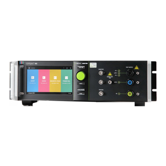
Page 36: Design And Functions
EM TEST Compact NX5 Design and Functions 4.1. Front view 11 CRO Trigger output 5V Active indication CRO V (surge) HV pulse Burst output 50 Touch screen 12 Start / Pause Knob (Inc. / Dec /Enter) Coupling (Power, Burst, Surge) 13 Stop "... - Page 37 EM TEST Compact NX5 11 CRO Trigger output 5V Active indication CRO V (surge) HV pulse Burst output 50 Touch screen 12 START / PAUSE Knob (Inc. / Dec /Enter) Coupling (Power, Burst, Surge) 13 STOP " Test On"...
-
Page 38: Rear View
It is not allowed to connect these outputs to any other coupling/decoupling network than manufactured by EM TEST. Before to connect any external networks to this output the operator must contact the manufacturer. Any damages due to this matter are not covered by warranty. - Page 39 EM TEST Compact NX5 1 Phase indication PF1 / PF2 7 Monitor V, Monitor I 13 Ethernet interface 2 EUT supply input 8 Fail, EUT 1, EUT2 14 Opto Link Interface 3 Surge output HV - COM 9 External Trigger IN...
- Page 40 EM TEST Compact NX5 1 Phase indication PF1 / PF2 7 Monitor V, Monitor I 13 Ethernet interface 2 EUT supply input 8 Fail, EUT 1, EUT2 14 Opto Link Interface 3 Surge output HV - COM 9 External Trigger IN...
-
Page 41: Menu Description
EM TEST Compact NX5 4.3. Menu description 4.3.1. Main Menu Home Returns to the Home screen Help Shows the Quick Start Guide for a brief information for NX5 generator operation EUT and Supply configuration - EUT configuration (power line arrangement / data lines) -
Page 42: Menu Setting
Equipment setup for External couplers, Transformers System Information Information Device Version, Firmware, Software Representative address EM TEST / AMETEK CTS offices, when touch the national flags CH, Germany, USA, Poland, France, Italy, Austria, China, Japan - Software update (3.6. Software... -
Page 43: Test Phenomena
EM TEST Compact NX5 4.3.3. Test phenomena Every phenomenon is supported by a color code. Touch into the colored field for select and load a test. The icon shows the kind of test phenomena. Burst impulse test 5/50 ns as per IEC 61000-4-4 Surge impulse test 1,2 /50 µs as per IEC 61000-4-5... - Page 44 EM TEST Compact NX5 4.3.3.1. Parameter setting All phenomena offer similar parameter setting procedures. The figure below explains the different actions for parameter setting. Parameter change All white colored parameters are changeable. Blue colored parameters are normally defined by the used standard and fixed.
- Page 45 EM TEST Compact NX5 Picture change The dots below the picture indicate the number and position of available pictures. Slide left or right through the picture for change to the next / previous picture. Coupling screen Touch the coupling symbol for open the coupling screen.
-
Page 46: Test And Run Window
EM TEST Compact NX5 4.3.4. Test and Run Window Test Window In the test window the user can enter the parameters of the test. Further it is possible to change in another test menu and to safe the test as Easy Link or User test. - Page 47 EM TEST Compact NX5 Block diagram for a test Test window: Yellow background Run Window: Grey background State machine for the generator screen during a test sequence Test window Menu Operating Manual V 1.06 47 / 143...
- Page 48 EM TEST Compact NX5 4.3.4.1. Run Window Menu The run Window Menu offers the following functions. The most functions are available in all phenomenon. View Run Information Run log table where all parameter changes and events during the test are logged.
-
Page 49: Eut Setup
EM TEST Compact NX5 4.3.5. EUT Setup In the EUT Setting the user specified his EUT. With this information the compact generator software will configure all settings to the EUT requirements. The user defines: Mode of supply voltage (AC/DC) Configuration of the EUT supply wiring... - Page 50 EM TEST Compact NX5 4.3.5.1. EUT Setup / TEST TEST Power configuration for the actual connected EUT Supply: Coupling: Power lines Data lines Phase Filter: Select the used lines - 1-phase (L, N, PE) - 3-phases (L1, L2, L3, N, PE)
- Page 51 EM TEST Compact NX5 Path Vnom (controlled at PF2) Any voltage (example 230 V- 10%) The variac voltage is set to the following voltages: Power Fail: settled DIP voltage Power magnetic Field: All other phenomenon’s: Vnom (PF2) NOTE: PF2 is used for operate a EUT with different voltage than the actual mains voltage.
- Page 52 EM TEST Compact NX5 4.3.5.4. RMS Measurement The built in RMS measurement measures the EUT voltage and current. During the surge coupling an ac current is flowing over the coupling capacitor through the surge wave shape circuit. This current is also measured by the rms meter and is to respect for the EUT reading.
-
Page 53: Setup
EM TEST Compact NX5 4.3.6. Setup The Setup menu is the place where the user configures his test equipment and device behavior. General: Setup menu for the NX system Equipment: Setup menu for equipment’s connected to the NX test generator... - Page 54 EM TEST Compact NX5 4.3.6.2. Setup / General / Date and Time menu Set Date: Year; Month and Day from calendar For set tap to the Year, Month (date) Date format: dd.mm.yyy; dd-mm-yyyy, dd/mm/yyyy, yyyy-mm-dd Set time: Hour; minute Time format: hh:mm:ss (24 h), hh:mm:ss (12 h) 4.3.6.3.
- Page 55 EM TEST Compact NX5 4.3.6.5. Setup / General / Sounds & Signals General sounds and signals level: Volume: Move the cursor to change Surge countdown signal: one beep signal Disable: no beep signal Enable: one beep signal approx. 1 s before trigger...
- Page 56 HV – COM capacitance: HV – COM output at rear side Default setting is “Enable”. When using an EM Test coupling device, the capacitor is automatically disabled. The recognized connected EM TEST 3-phase CDN has already a built in 18 µF capacitor.
- Page 57 EM TEST Compact NX5 4.3.6.7. Setup / General / Report Report menu is implemented on version 3.0.0.0. and higher Individual setting for: - Generator report - Test report number - Customer name - EUT name General Report generation, - Climatic condition of the EUT during test...
- Page 58 EM TEST Compact NX5 Report Style The user can load a logo that will be implemented in the report. Supported Formats: png, jpg Max. file size: 200 kBytes Report Style (loaded logo) Indication for implement the picture in the report...
- Page 59 EM TEST Compact NX5 4.3.6.11. Setup / Equipment / Transformers Define and load an external transformer Variable Motorized variac transformer Tapped Tapped transformer H-Field Magnetic field current transformer Default transformer Library Variable Transformer: variac NX1-260-16 variac NX1-260-32 Tapped Transformer: V 4780...
-
Page 60: Test Link
EM TEST Compact NX5 4.3.7. TEST Link In this menu the user creates and complete his own “Test Link” TEST LINK A “Test Link” is generated from Test files, loaded from the library (Burst, Surge…) Pause or messages with information to... - Page 61 EM TEST Compact NX5 4.3.9.1. Select the output path where to couple the impulse To define at which device the generated pulse to applies, the user must configure it in the system. This happens in the menu Devices and Modules...
-
Page 62: Information
EM TEST Compact NX5 4.3.10. Information System Information Information Device Version, Firmware, Software Representative address EM TEST / AMETEK CTS offices, when touch the national flags CH, Germany, USA, Poland, France, Italy, Austria, China, Japan Software update menu (see chapter software update) 3.6. -
Page 63: Service
Service The addresses of the EM TEST (Switzerland) GmbH and the EM TEST locations are shown. The addresses of all EM TEST sales agencies are listed on the web site of EM Test under : www.emtest.com Operating Manual V 1.06... -
Page 64: Variable Voltage Transformers Adjustment Procedure
EM TEST Compact NX5 4.5. Variable voltage transformers adjustment procedure The compact NX5 is able to control an external voltage source with a 0-10V analogue dc signal. The 10V level corresponds to the max. output voltage of the connected voltage source. For the correct setting it is necessary to know the max. -
Page 65: Adjustment Procedure For Variable Transformers
EM TEST Compact NX5 4.5.1. Adjustment procedure for variable transformers For adjust a variac transformer, select first the device to adjust in: Menu / Setup / Transformers / Variable 1. Select CHANGE or make a Long click into the device for change into the software setup. - Page 66 EM TEST Compact NX5 Check at Vnom (230 V) level. variac output voltage - Settled nominal voltage: (230 V) 230V/Max. voltage *10.00 V - Output (0-10 V) voltage: Read the value at the voltmeter and check if the value is inside the tolerance of ± 4 V...
-
Page 67: Adjustment Procedure For Tapped Transformers With Analogue Dc Control Voltage
EM TEST Compact NX5 4.5.2. Adjustment procedure for tapped transformers with analogue DC control voltage For adjust a tapped transformer, select first the device to adjust in: Menu / Setup / Transformers / Variable The tapped transformer is programmed that the nominal voltage corresponds to 10.0V dc as 100% for... -
Page 68: Test Equipment Compact Nx5 N
EM TEST Compact NX5 Test Equipment compact NX5 N The simulator compact NX5 N is separated in different main parts. The control unit is screened to all other parts. 5.1. compact NX5 Control unit Power supply 1 App board controller... -
Page 69: Technical Data
EM TEST Compact NX5 Technical data 6.1. EFT Electrical Fast Transients Burst as per IEC 61000-4-4 Test Level Model N5 200 V – 5500 V ± 10% Step 1 V Open circuit * 100 V – 2750 V Wave shape into a 50 load Rise time tr 5 ns ±... -
Page 70: Surge Immunity Requirements As Per Iec 61000-4-5
EM TEST Compact NX5 6.2. SURGE Immunity requirements as per IEC 61000-4-5 Test Level compact NX5 (16A Models) compact NX5 (32 A Models) 160 V – 5000 V ± 10% Step 1 V Open circuit voltage 80 A – 2500 A ± 10%... -
Page 71: Pulsed Magnetic Field As Per Iec 61000-4-9
EM TEST Compact NX5 6.3. Pulsed magnetic Field as per IEC 61000-4-9 Test Level Model NX5 160 V – 5000 V ± 10% Step 1 V Generator charging voltage 80 A – 2500 A ± 10% Short circuit current Approx. 80 A/m to 2500 A/m Wave shape 8 s ±... -
Page 72: Power Fail Generator As Per Iec 61000-4-11
EM TEST Compact NX5 6.4. Power Fail Generator as per IEC 61000-4-11 EUT supply Model NX5 Other models NX series Channel PF1 and PF2 AC voltage/current max. 300V/16 A Up to max. 400 V/ 32 A Mains frequency 50/60 Hz DC voltage/current max. -
Page 73: Eut Supply Specifications
EM TEST Compact NX5 6.5. EUT Supply Specifications Standard models Model Remarks compact NX5 300V 16A 1- phase DC 300 V / 16 A EUT Fuse The compact NX5 models have no internal fuse for the EUT supply. The user is responsible to adapt a suitable fuse for the EUT outside the compact NX5 6.6. -
Page 74: Maintenance Setup And Service
EM TEST Compact NX5 Maintenance setup and service 7.1. General Inside the test system there are no adjustable elements accessible to the user neither for calibration nor for maintenance purpose. The housing of the test system must not be opened. Should any maintenance or adjustment become necessary, the whole test system, together with an order or fault report, should be sent to an AMETEK CTS service center. -
Page 75: Calibration And Verification
EM TEST equipment. EM TEST doesn’t know each customer’s Quality Assurance Policy nor do we know how often the equipment is used and what kind of tests are performed during the life cycle of a test equipment. Only the customer knows all the details and therefore the customer needs to specify the calibration interval for his test equipment. -
Page 76: Delivery Groups
ESA Adapter for adapt different power mains connectors As accessories adapters to different power mains connectors are part of the delivery of EM TEST surge generators. E.g. these are adaptors for Schuko - US - AUS - UK power mains connectors. - Page 77 EM TEST Compact NX5 Surge Power Fail V4780 transformer with taps - Transformer with taps at 40%&, 70%, 80% - 230V / 16A Variac NX-1-260-16 - Motorvariac 0-260 V / 16 A or 32 A - Control signal 0-10 Vdc.
-
Page 78: Eft Burst As Per Iec 61000-4-4
EM TEST Compact NX5 EFT Burst as per IEC 61000-4-4 Burst Module 5/50 ns If the user reduces the test voltage in Quick Start or in the Manual Standard Test Routine, the storage capacitor will be discharged only by the burst pulses. The result is a higher test voltage on the EUT than indicated on the display until the storage capacitor is discharged to the preselected value. -
Page 79: Quick Start
EM TEST Compact NX5 9.1.1. Quick Start Easy and very fast operation of all standard functions of the equipment. The latest simulator settings are stored automatically and will be recalled when Quick Start is next selected. Quick Start Menu Quick Start Menu... -
Page 80: Standard Test Routines
EM TEST Compact NX5 9.1.2. Standard test routines The user can select preprogrammed standard test routines. Standard Menu Within this test routine all standard parameters can be changed online during testing at the 1-phase and coaxial 50 Ω output of the compact NX5 generator. This procedure therefore is very easy and fast to use. -
Page 81: Extended Test
EM TEST Compact NX5 9.1.3. Extended Test The extended menu offers various useful tests for testing and development. Extended Menu Voltage iteration stepwise Voltage change after T by V The test voltage is increased from V1 to V2 by steps of V after the defined test time T. All limitations are the same as defined under Quick Start. -
Page 82: Max Burst Impulses / S
EM TEST Compact NX5 Synchronized with a fixed phase angle The burst is triggered with respect to the phase angle of the power supply connected to the Sync input at the rear panel of the equipment. The power supply must be an AC voltage with a nominal frequency of 16 to 500Hz. -
Page 83: Burst Menu
EM TEST Compact NX5 9.2. Burst Menu Burst Menu Button for open and close the Burst Menu Change to other Burst test routines. The last used test in this routine will be loaded. - Quick Start - Standards - Extended Tests... -
Page 84: Configuration
EM TEST Compact NX5 9.2.1. Configuration In the configuration menu the user set the following parameters: - Trigger out signal at the BNC plug on generator front side - Start trigger for the impulse or event on the BNC Ext. Trigger plug on rear side or blinking Start button - Behavior of the EUT Monitor 1 and EUT Monitor 2 on BNC plug on rear side 9.2.1.1. - Page 85 EM TEST Compact NX5 9.2.1.2. Signal Trigger The Signal Trigger occurs by pressing the blinking START / PAUSE button or with an external trigger positive slope signal at the rear side BNC Ext. Trigger plug. The start trigger offers the following status:...
- Page 86 EM TEST Compact NX5 EUT Monitor input signal EUT Monitor Input BNC plug on rear side of the compact NX generator Status of BNC input of EUT monitor 1 / 2 Input signal Open collector signal 15 V to 0 V negative slope Triger level 2 V ±1 V...
-
Page 87: Burst Generation
EM TEST Compact NX5 9.3. Burst generation Burst switch: The discharge switch is a highly reproducible semiconductor switch. Spike frequencies up to 1000 kHz are by a factor of 10 higher than recommended in the actual EFT standards. This means of course that also the pulse energy would be 10 times higher. -
Page 88: Coupling/Decoupling Network
EM TEST Compact NX5 9.5. Coupling/decoupling network The decoupling part of the coupling network has to: - filter the interference pulses in the direction to the power supply; - protect other systems that are connected to the same power supply and - realize a high impedance of the power supply, e.g. -
Page 89: Burst Test Setup
EM TEST Compact NX5 9.6. Burst Test Setup - The test generator and the coupling network should be connected to the reference ground plane (acc. to high frequency requirements). - The equipment under test must be isolated from the reference ground plane. The distance should be 10 cm. -
Page 90: Test Setup With Capacitive Coupling Clamp
EM TEST Compact NX5 9.6.1. Test setup with capacitive coupling clamp When using the coupling clamp, the minimum distance between the coupling plates and all other conductive surfaces (including the generator), except the ground reference plane beneath the coupling clamp and beneath the EUT, shall be at least 0.5 m. -
Page 91: Surge Immunity As Per Iec 61000-4-5
EM TEST Compact NX5 Surge Immunity as per IEC 61000-4-5 Surge Module 1.2/50s – 8/20s The internal coupling network is designed for mains frequency 50 Hz / 60 Hz. When L – N coupling is selected an additional current of approx. 1.5 A flows, caused by the 18 F coupling capacitor and the pulse forming network. -
Page 92: Quick Start
EM TEST Compact NX5 10.1.1. Quick Start Easy and very fast operation of all standard functions of the equipment. The latest simulator settings are stored automatically and will be recalled when Quick Start is next selected. Quick Start Menu While a test is running the user can select parameters. The selected parameter then can be changed online with the inc/dec knob. - Page 93 EM TEST Compact NX5 Iteration of the standard test procedure as per IEC 61000-4-5 The surges have to be applied synchronized to the voltage phase at the respective angle and the peak value of the a.c. voltage wave (positive and negative).
-
Page 94: User Test Routines
EM TEST Compact NX5 10.1.3. User Test Routines The user can program, save and recall his own specific test routines. The next pages show the selection of the functions. The extended menu offers various useful tests for testing and development. - Page 95 EM TEST Compact NX5 This Function is actually not implemented ANSI A coupling after n pulses The coupling mode with 12Ω und 9µF will automatically be changed after the preselected number of pulses has been released. All possible coupling modes will be selected. The same parameters as under Quick Start can be selected.
-
Page 96: Surge Menu
EM TEST Compact NX5 10.2. Surge Menu Surge Menu Button for open and close the Surge Menu Change to other Surge test routines. The last used test in this routine will be loaded. - Quick Start - Standards - Extended Tests... -
Page 97: Surge Pulse Settings
EM TEST Compact NX5 10.3. Surge pulse settings 10.3.1. Configuration In the configuration menu the user set the following parameters: - Trigger out signal at the BNC plug on generator front side - Signal trigger for the impulse or event on the BNC Ext. Trigger plug on rear side or blinking Start... - Page 98 EM TEST Compact NX5 10.3.1.2. Start Trigger The Start Trigger occurs by pressing the blinking START / PAUSE button or with an external trigger positive slope signal at the rear side BNC Ext. Trigger plug. The start trigger offers the following status:...
- Page 99 EM TEST Compact NX5 10.3.1.3. EUT Monitor The EUT monitor 1 and EUT Monitor 2 input is used for control the compaxt NX device according the EUT behavior. Each input is programmable to have different events as: Disabled No function Notify Makes a mark in the NX software.
-
Page 100: Setup Current Peak Limiter For Surge Current
EM TEST Compact NX5 10.3.2. Setup current peak limiter for surge current The peak current limiter stops the test run when during a test the measured peak current of a surge pulse is higher than the preselected current value. This safety function protects the EUT for further surge pulses that can become any dangerous situation. -
Page 101: Hv-Com Output (18 Μf Capacitor)
HV-COM output (18 µF capacitor) The HV – COM output includes a configurable output capacity with 18 µF. Using EM TEST coupling-decoupling networks, the coupling capacitor is part of the CDN. For other applications e.g. pulsed surge magnetic field or a surge verification requires an 18 µF capacitor in the circuit. -
Page 102: Surge Pulse Application
EM TEST Compact NX5 10.4. Surge pulse application 10.4.1. Phase synchronization in 3-phase system The synchronization in a 3-phase coupler system is taken from the phase L1 and neutral. In case of a delta supply without neutral connected, an artificial neutral point is defined by a high impedance network. -
Page 103: Surge Pulse Application
EM TEST Compact NX5 10.5. Surge pulse application Discharge switch: The discharge switch is a highly reproducible semiconductor switch. 10.6. Coupling/decoupling network The coupling network has to couple the interference pulses to the lines of a power supply system (AC or DC). -
Page 104: Coupling To I / O Lines
EM TEST Compact NX5 10.6.2. Coupling to I / O lines The coupling to I/O lines is generally realized with other coupling networks than for power supply lines. The loading of the I/O lines with big coupling capacitors is mostly not possible. -
Page 105: Magnetic Field Test As Per Iec 61000-4-9
EM TEST Compact NX5 Magnetic field test as per IEC 61000-4-9 Pulsed Magnetic field as per IEC 61000-4Surge Module 1.2/50s – 8/20s Main Menu Magnetic Field The internal coupling network is designed for mains frequency 50 Hz / 60 Hz. -
Page 106: Pulsed Magnetic Field As Per Iec 61000-4-9
EM TEST Compact NX5 11.1. Pulsed Magnetic field as per IEC 61000-4-9 The menu offers different test routines for pulsed magnetic field testing. Main Menu Pulsed Magnetic Field The Magnetic Field menu offers different test routines for pulsed magnetic testing. - Page 107 EM TEST Compact NX5 For magnetic field testing the antenna correction factor shall be included. The operator can enter this factor within the setup menu under the service routine. Setup pulsed magnetic Test field Disconnect all power cables on the rear side at the Test supply plugs.
-
Page 108: Voltage Dips And Interruptions As Per Iec 61000-4-11
EM TEST Compact NX5 Voltage Dips and Interruptions as per IEC 61000-4-11 Main Menu Power Fail for voltage dips and interrupt tests and voltage variation 12.1. Test setup for DIPS and Interruption tests Voltage DIPS For voltage DIPS a connection must be made from the compact NX PF2 input to the motorvariac PF2 or V4780, where the reduced voltage is present. - Page 109 EM TEST Compact NX5 Setup for dU mode The generator is connected as follow: PF1: Mains voltage from the grid PF2: Reduced voltage preset for the dip test. Mostly set to 40%, 70% or 80% of the mains voltage The internal generator switch will change the EUT supply voltage between PF1 and reduced PF2 voltage.
-
Page 110: Operation
EM TEST Compact NX5 12.2. Operation Dips Module for voltage Dips and short interruptions. The menu offers different test routines for pulsed magnetic field testing. Main Menu Power Fail for voltage dips and interrupt tests The Power Fail menu offers different test routines for voltage dips and interrupt testing. -
Page 111: Quick Start
EM TEST Compact NX5 12.2.1. Quick Start Easy and very fast operation of all standard functions of the equipment. The latest simulator settings are stored automatically and will be recalled when Quick Start is next selected. Explanations Phase angle Duration of a single event Repetition rate (time between two events) Channel select (PF1, PF2 or V) -
Page 112: Standard Test Routines
EM TEST Compact NX5 12.2.2. Standard Test Routines 12.2.2.1. IEC 61000-4-11 (AC power supply mains) As long as the external transformer variac NX1-260-16 is used, controlled by an analogue 0-10V control voltage, the test is conducted automatically. If this option is not available the manual test routine shall be used. -
Page 113: Extended Tests
EM TEST Compact NX5 12.2.3. Extended Tests Angle iteration stepwise After n events the phase angle related to which the events are released will change from A1 to A2 by steps of A until A2 is reached. The same parameters as under Quick Start can be selected. -
Page 114: Voltage Variation
EM TEST Compact NX5 12.3. Voltage Variation Voltage variation as per IEC 61000-4-11 (2004) An external power source or motor driven variac is controlled by a 0-10V control signal. The operator can select the time per voltage level, the ramp up and ramp down of the voltage change and the voltage levels itself. -
Page 115: Power Fail Menu
EM TEST Compact NX5 12.4. Power Fail Menu Burst Menu Button for open and close the Power Fail Menu Change to other power Fail test routines. The last used test in this routine will be loaded. - Quick Start - Standards... -
Page 116: The Power Fail Test
EM TEST Compact NX5 12.5. The Power Fail Test 12.5.1. Test routines termination The test routine for power fail starts with an event with the duration (td), followed by a repetition time (tr). For operating, the compact NX generator has the following handling for the test routine... -
Page 117: Overcurrent
EM TEST Compact NX5 12.6. Overcurrent Power switches The power switches are electronically protected against overload and short- circuits. The nominal current of the switches is 25 A. Special protection requirements of the EUT must be separately assured by the user. -
Page 118: The Power Fail Test
EM TEST Compact NX5 12.7. The Power Fail Test The generator type compact NX5 N5/N7 simulates the following interference : - Voltage dips - Voltage interruptions - Voltage variations - Inverse 12.7.1. Voltage Interruptions Depending on the preselected test parameters at the front panel of the simulator the power supply for the EUT is interrupted for a certain time and at a certain phase angle (AC power supplies). -
Page 119: Voltage Dips, Voltage Variations
EM TEST Compact NX5 12.7.2. Voltage dips, voltage variations Depending on the preselected test parameters, the test voltage is changed to a higher or to a lower value for a certain duration and at a certain phase angle. Voltage variations are normally related to the nominal value of the supply voltage. Therefore two different variacs shall be connected at the rear side of the simulator. -
Page 120: Test Setup And Accessories
EM TEST Compact NX5 12.9. Test setup and accessories 12.9.1. Transformer type V4780 The transformer shall be used to generate under-voltages in ac power supply systems. According to the IEC 61000- 4-11 and the EN 50081-2 voltage dips shall be generated as shown in fig. below. Different test levels are recommended 12.9.1.1. - Page 121 EM TEST Compact NX5 12.9.1.4. Technical Data V 4780 models Design Tapped auto-transformer with 40%, 70%, 80%, 100 % output voltage Input: Voltage Uin: max. 250 V Frequency 50/60Hz Tap selection manually (V4780 ) banana plugs for 40%, 70%, 80% Remote control 0.10V dc (V4780 S2) for 40%, 70%, 80%...
-
Page 122: Variable Transformer Variac Nx1-260-16
EM TEST Compact NX5 12.9.2. Variable Transformer variac NX1-260-16 The motor variac can be used to simulate power supply failures as under-voltages, voltage interruptions and voltage variations. The basic standard IEC 61000-4-11 and the generic standard EN 61000-6-2 are specifying these phenomena. - Page 123 EM TEST Compact NX5 12.9.2.3. Technical data Motorvariac variac NX-1-260-16 Input: Voltage Vin: max. 250 V Frequency 50/60 Hz Output Vout: 0 – 260 V for channel PF2 Voltage variable Voltage fix Vout: Vin for channel PF1 Current max: 16 A Power 0 - 4.1 kVA...
-
Page 124: Power Frequency Magnetic Field As Per Iec 61000-4-8
EM TEST Compact NX5 Power frequency Magnetic Field as per IEC 61000-4-8 Main Menu Magnetic Field separated to “Power frequency” and “Pulsed” Required Device settings to perform a power frequency magnetic field test For perform a 50/60 Hz magnetic field test, the NX5 generator must be configured with the used hardware in the... -
Page 125: Magnetic Field As Per Iec 61000-4-8
EM TEST Compact NX5 13.1. Magnetic field as per IEC 61000-4-8 The menu offers different test routines for power frequency magnetic field testing. Main menu ac powered magnetic field The Magnetic Field menu offers different test routines for pulsed magnetic testing. - Page 126 EM TEST Compact NX5 Test setup For magnetic field testing the power mains input at PF1 shall be disconnected.; 230 V/16 A. Warning The voltage V is adjusted with a variac as long as the required antenna current is available and the related H field is generated in the center of the magnetic field antenna.
- Page 127 EM TEST Compact NX5 Test setup with MC 26100 for H-Fields up to 1000A/m Schematics Test setup Schematics and Test setup with compact NX5, variac NX1-260-16, MC 26100 and MS 100N Option for required magnetic field tests as per IEC 61000-4-8...
-
Page 128: Telecom Surge Immunity As Per Iec 61000-4-5
EM TEST Compact NX5 Telecom Surge Immunity as per IEC 61000-4-5 Surge Module 10/700s – 8/20s The internal coupling network is designed for mains frequency 50 Hz / 60 Hz. When L – N coupling is selected an additional current of approx. 1.5 A flows, caused by the 18 F coupling capacitor and the pulse forming network. -
Page 129: Quick Start
EM TEST Compact NX5 14.1.1. Quick Start Easy and very fast operation of all standard functions of the equipment. The latest simulator settings are stored automatically and will be recalled when Quick Start is next selected. Quick Start Menu While a test is running the user can select parameters. The selected parameter then can be changed online with the inc/dec knob. -
Page 130: Extended Test Routines
EM TEST Compact NX5 14.1.3. Extended Test Routines The user can program, save and recall his own specific test routines. The next pages shows the selection of the functions. The extended menu offers various useful tests for testing and development. -
Page 131: Generator Network For Telecom Surge
EM TEST Compact NX5 14.1.4. Generator Network for Telecom Surge The figure below shows the elements and schematic of the Telecom Surge pulse circuit T1 to T4 Ports for direct application HV, COM Port to external coupling network Operating Manual V 1.06... -
Page 132: Telecom Surge Menu
EM TEST Compact NX5 14.2. Telecom Surge Menu Telecom Surge Menu Button for open and close the Telecom Surge Menu Change to other Surge test routines. The last used test in this routine will be loaded. - Quick Start - Standards... - Page 133 EM TEST Compact NX5 14.3.1.1. Trigger OUT The trigger out signal is a programmable 5V edge signal located at the front side BNC Trigger plug. This signal is for trigger other devices like oscilloscopes or other devices. The generator offers the following trigger out...
- Page 134 EM TEST Compact NX5 14.3.1.2. Start Trigger The Start Trigger occurs by pressing the blinking START / PAUSE button or with an external trigger positive slope signal at the rear side BNC Ext. Trigger plug. The start trigger offers the following status:...
-
Page 135: Report
EM TEST Compact NX5 Report General The NX application software generates during each test an internal log-file with all parameter settings and all actions during the test. This log file will be used for generate the report after the test. After the test following procedures are possible: The program starts to generates the report when “generate Report”... -
Page 136: Report Setting
EM TEST Compact NX5 15.2. Report setting The detailed report setting description is in chapter 4.3.6.7. Setup / General / Report. Below you see the overview about the report configuration Operating Manual V 1.06 136 / 143... -
Page 137: Report Export
EM TEST Compact NX5 15.3. Report Export The detailed report setting description is in chapter 4.3.6.7. Setup / General / Report. Below you see the overview about the report configuration Used file extensions Operating Manual V 1.06 137 / 143... -
Page 138: Appendix
EM TEST Compact NX5 Appendix 16.1. Declaration of CE-Conformity 16.1.1. CE-Conformity compact NX5 EM TEST (Switzerland) GmbH Manufacturer : Address: Sternenhofstr. 15 CH 4153 Reinach BL1 Switzerland declares, that under is sole responsibility, the product’s listed below, including all their options, are conformity with the applicable CE directives listed below using the relevant section of the following EC standards and other normative documents. -
Page 139: Ce-Conformity V4780
EM TEST Compact NX5 16.1.2. CE-Conformity V4780 EM TEST (Switzerland) GmbH Manufacturer : Address: Sternenhofstr. 15 CH 4153 Reinach BL1 Switzerland declares, that under is sole responsibility, the product’s listed below, including all their options, are conformity with the applicable CE directives listed below using the relevant section of the following EC standards and other normative documents. -
Page 140: Ce-Conformity V4780
EM TEST Compact NX5 16.1.3. CE-Conformity V4780 EM TEST (Switzerland) GmbH Manufacturer : Address: Sternenhofstr. 15 CH 4153 Reinach BL1 Switzerland declares, that under is sole responsibility, the product’s listed below, including all their options, are conformity with the applicable CE directives listed below using the relevant section of the following EC standards and other normative documents. -
Page 141: Compact Nx5 General Diagram
EM TEST Compact NX5 16.2. compact NX5 General Diagram 16.3. Main diagram control connection Operating Manual V 1.06 141 / 143... -
Page 143: Main Diagram High Voltage Connection
EM TEST Compact NX5 16.4. Main diagram high voltage connection Operating Manual V 1.06 143 / 143...
Need help?
Do you have a question about the compact NX5 Series and is the answer not in the manual?
Questions and answers