Table of Contents
Advertisement
Quick Links
emc test equipment
M a n u a l
f o r
O p e r a t i o n
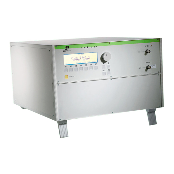
Continuous Wave Simulator
Type CWS 500D
Compact RF simulator for BCI, Stripline and TEM cell
applications. 10kHz – 400MHz ( 1000MHz)
The CWS500D is the state of the art solution in a
compact one-box design to test immunity to
conducted disturbances induced by radio frequency
fields. The CWS500D includes signal generator, RF
amplifier directional coupler, 3 channel power meter,
software and GPIB interface.
The integrated amplifier can also be controlled by an
external signal generators. ICD software supports the
test routines and controls external measuring
devices.
Version: 1.07 / 18.01.2007
Replaces: 1.06 / 28.06.2006
Filename: manual CWS500D V107.doc
Printdate: 18.01.07
C
•
ISO 11452 part 4
•
ISO 11452 part 5
•
RTCA DO 160D
•
Mil 461 CS 114
•
EN/IEC 61000-4-6
•
various automotive
manufacturer's
specifications
Advertisement
Table of Contents

Related Manuals for EM TEST CWS 500D


Summary of Contents for EM TEST CWS 500D
- Page 1 M a n u a l f o r O p e r a t i o n Continuous Wave Simulator Type CWS 500D Compact RF simulator for BCI, Stripline and TEM cell • ISO 11452 part 4 applications. 10kHz – 400MHz ( 1000MHz) •...
-
Page 2: Table Of Contents
8.1. General..............................31 8.2. Calibration and verification........................31 8.2.1. Factory calibration...........................31 8.2.2. Guideline to determine the calibration period of EM Test instrumentation ..........31 8.2.3. Calibration of Accessories made by passive components only: .............31 8.2.4. Periodically In-house verification......................31 Delivery Groups ............................32 9.1. Basic equipment............................32 9.2. -
Page 3: Safety Aspects
Below are all possible connections to the CWS 400MHz model figure 2.1 1000MHz model figure 2.2 Fig 2.1 : CWS 500D (400MHz) connection rear view Fig 2.2 : CWS 500D ( 1 GHz) connection rear view Test Setup CWS 500D 2.2. Figure 2.3a / 2.3b :... -
Page 4: Part Identifications And Functions
EM Test CWS500 D 2.3. Part Identifications and Functions Continuous Wave Simulator CWS 500D 400MHz CWS 500D 1GHz Fig 2.4 2.3.1. Clamp Applications for Automotive standards Bulk Current Injection Clamp BCI type ( selection of clamps) F-130-A1 10kHz – 400MHz F-120- 6A 10kHz –... -
Page 5: Cdn Applications As Per Iec 61000-4-6
EM Test CWS500 D 2.3.2. CDN Applications as per IEC 61000-4-6 Bulk Current Injection Clamp BCI type F-120-9A 10kHz – 230MHz FCC-BCICF-4 Calibration Fixture for BCI clamp (jig) Fig 2.11 Attenuator 6 dB / 75W Fig 2.12 Coupling / Decoupling Network Types: CDN-M 1;... -
Page 6: Operating Functions
EM Test CWS500 D Operating Functions 3.1. Front View Fig 3.1 Display LED RF Output Monitor Cursor keys "←" and "→" Function keys "F1..F7" 10. Current Probe Input (Monitor) Exit "Test On" 11 LED Current Probe Input Escape Knob (Inc / Dec) -
Page 7: Rear View Cws 500D 400Mhz Model
The BNC input FAIL 1 can be used for failure detection on the EUT. If the input is set to ground (chassis), the CWS 500D generator will be stopped and finish the test routine. It is not possible to continue the test. -
Page 8: Rear View Cws 500D 1Ghz Model
The BNC input FAIL 1 can be used for failure detection on the EUT. If the input is set to ground (chassis), the CWS 500D generator will be stopped and finish the test routine. It is not possible to continue the test. -
Page 9: Front Panel Operation
EM Test CWS500 D Front Panel Operation 4.1. Basic Operations The simulator is operated by an easy menu control system. Seven function keys are available to select parameters and Fig 4.1 functions. The selected parameter is blinking and can be changed by turning the knob (incr./decr.). -
Page 10: Quickstart
EM Test CWS500 D 4.2. Quickstart Easy and very fast operation for functions check and verification of the CWS 500D. Page 2 (Show Parameters) Page 3 (Change) Quickstart Quickstart = 63,0 dB 109.500 MHz Mod = AM 1kHz 80% Att : 0.0 dB -... -
Page 11: Quickstart During Instrument Calibration
EM Test CWS500 D 4.2.1. Quickstart during instrument calibration This function needs Firmware 2.11 or higher. In case of a calibration of the measuring instrument it is necessary to use external signal generators. The CWS instrument has frequency matched calibration curfes for each instrument channel. When using the internal signal generator CWS 500 knows the actual frequency and select automatically the correct reference. -
Page 12: Display During Remote Control
EM Test CWS500 D 4.3. Display during Remote control The CWS 500 can only work with remote control from the ICD software Version 3.00 or higher. During the operation the following information appears on the display: Remote control R E M O T E ProgRemote = 5.420MHz... -
Page 13: Modulation
EM Test CWS500 D 4.3.1. Modulation Modulation as per IEC Figure 4.3 shows the modulation for IEC application. Fig 4.3 : Unmodulated 80% AM Pulse modulation Modulation as per ISO Modulation signal as per ISO, peak conservation ( pulse) standard. These... -
Page 14: Service
F5 : Function check powermeter F6 : Function check amplifier switch F1 Addresses The addresses of EM TEST AG Switzerland and EM Test GmbH Germany will be displayed. A list of the world-wide sales partners is awailable on the internet under www.emtest.com. F3 Setup The software will clearly explain the setup procedure. -
Page 15: Setup
F4 Keyboard Beeper F4 selects the beeper ON/OFF mode. F5 Timer By pressing F5 will display the total operating time of the CWS 500D will be displayed. 4.4.3. Amplifier Switch Change of the used amplifier internal or external Page 3 (Amplifier Switch) -
Page 16: Starting Operation
The RF voltages on the center pin of the RF output connector can be hazardous. The RF output connector must be connected to a load before AC power is applied to the CWS 500D. Do not touch the center pin of the RF output connector or accessories which are connected to it. -
Page 17: Generator Function Check
5.2. Generator Function Check As with all testing equipment, the continuous wave simulator type CWS 500D should be checked for performance and accuracy from time to time. The check should be completed as listed below. - Connect the RF-output of the CWS 500D to the 3dB-attenuator or an adequate attenuator. -
Page 18: Function Check Internal Powermeter
EM Test CWS500 D 5.3. Function Check internal Powermeter This function is for checking the built in 3-channel powermeter e.g. Forward Power and Rev Power and current monitor. Within this measuring procedure the measured values are compared with some nominal values, this in order to verify the correct function of the three measuring inputs. -
Page 19: Function Check Amplifier Switch ( 1Ghz Model Only)
EM Test CWS500 D 5.4. Function Check amplifier switch ( 1GHz model only) This function is for checking the correct operation of the built in amplifier switch. During this test the output connector at the frontside should be left open. -
Page 20: Calibration
EM Test CWS500 D 5.5. Calibration 5.5.1. Calibration Setup for Bulk Current Injection Clamp (BCI) as per ISO / DO / MIL Fig 5.5 : Calibration setup with BCI During calibration of the test setup on a ground reference plane at very low levels (very low currents) is important. -
Page 21: Calibration Setup Em Test And Iec 61000-4-6
5.5.2. Calibration Setup EM TEST and IEC 61000-4-6 The setup for calibration according to IEC 61000-4-6 is shown in the figure 5.7. below. EM Test has carefully tested the calibration setup and propose to eliminate the 150Ω terminating resistor on the AE port for CDN calibration. -
Page 22: Calibration Setup With Cdn
EM Test CWS500 D 5.5.3. Calibration Setup with CDN Maximum Voltage on the Monitor INPUT U = 13 dBm Make sure CDN and the 150Ω to 50Ω adapter are well connected to the ground reference plane (i.e. by using copper tape). -
Page 23: Calibration Setup With Em Clamp
EM Test CWS500 D 5.5.4. Calibration Setup with EM Clamp The calibration with an EM Clamp is similar to the CDN calibration. Fig 5.14 : Calibration setup with EM Clamp Make sure to connect the EM clamp correctly in the test and calibration setup. -
Page 24: Test Equipment Cws 500D
EM Test CWS500 D Test Equipment CWS 500D The CWS 500D continuous wave simulator is divided into three main parts. The control unit is completely separated and uncoupled from the RF power section. Fig 6.1 Control unit Transformer Power Supply Filter... -
Page 25: Control Unit
Fig 6.4 : ATT 3/100 The attenuator is required in some standards. However, the included amplifier will work correctly with any load. Although the CWS 500D can also be used correctly without the attenuator for high current application the 3dB can not be used! User manual V 1.07... -
Page 26: Cdn Coupling/ Decoupling Network
EM Test CWS500 D 6.5. CDN Coupling/ Decoupling Network The CDN’s are connected externally to the output of the simulator or the 6dB-attenuator. The coupling network is used to couple the disturbance signal to the lines of the equipment under test. The coupling is accomplished with capacitors or resistors having a sufficient bandwidth according to IEC 61000-4-6. -
Page 27: Test Setup With Cdn's
4. The EUT must be separated by 100mm (4 inches) from the ground reference plane. 5. The coaxial cables must be as short as possible. It is recommended to use the cables provided by CWS 500D. 6. The 50Ω matching resistor must be an adequate RF type. -
Page 28: Test Setup With The Current Monitor
EM Test CWS500 D 6.7. Test Setup with the Current Monitor Maximum Voltage on the MONITOR INPUT V = 13dBm Fig 6.13: Test Setup current monitoring probe With the CWS500D and the built-in Powermeter PM tests with current clamp ( BCI) or with EM clamps are easily made whatever with or without DUT current monitoring. -
Page 29: Technical Data
EM Test CWS500 D Technical Data Test Level: Output power 100W (nominal) Output impedance 50 Ohm, VSWR 2.0 : 1 nominal Level approx. -13dBm ... 50dBm Amplifier Class A, Gain > 52dB Current 4MHz ... 400MHz max. 700mA ( 100W amplifier, without attenuator, F-130A clamp ) - Page 30 EM Test CWS500 D Interfaces Serial RS 232 Baudrate 1200 - 19600 baud Parallel IEEE 488 GPIB interface Addresses 1 - 30 selectable All interfaces are included as standard features. Powermeter PM 1000 Frequency range 10kHz – 1000 MHz Input range Monitor -45 dBm ...
-
Page 31: Maintenance
Please refer to the corresponding standard before carrying out a calibration or verification. The standard describes the procedure, the tolerances and the the necessary auxiliary means. Suitable calibration adapters are needed. To compare the verification results, EM Test suggests to refer to the waveshape and values of the original calibration certificate. -
Page 32: Delivery Groups
To IEC 61000-4-6 Current Probe acc. IEC 61000-4-6 Cal adapters For all types of CDN’s and clamps ( manufactured and delivered by EM Test ) ATT 6/75 Attenuator 6dB / 75 W R-100 150 to 50 Ohm Adaptor... -
Page 33: Appendix
EM Test CWS500 D Appendix 10.1. Blockdiagram Blockdiagram CWS 500 D Fig 10.1 User manual V 1.07 33 / 34... -
Page 34: Declaration Ce- Conformity
CE directives listed below using the relevant section of the following EC standards and other normative documents. Product‘s name: Continuous Wave Simulator Model Number(s) CWS 500, CWS 500D, CWS 500D PM Low Voltage Directive 73/23/EEC Standard to which conformity is declared: EN 61010-1 Safety requirements for electrical equipment for measurement, control, and laboratory use.
Need help?
Do you have a question about the CWS 500D and is the answer not in the manual?
Questions and answers