Table of Contents
Advertisement
Quick Links
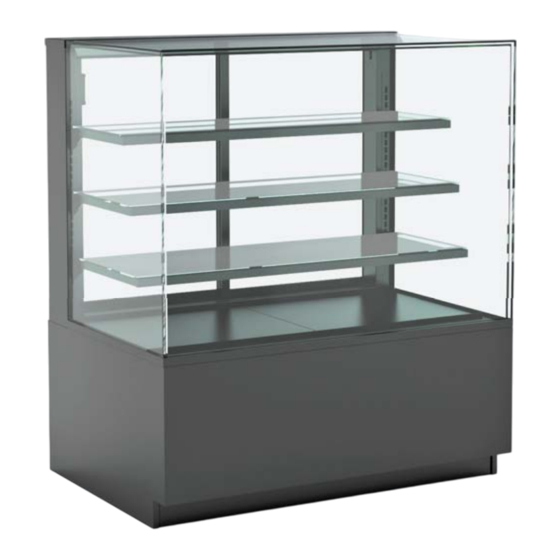
Reveal® User Manual
P A R T N U M B E R : 2 1 - 3 3 8 2 9
Please Note
Your specifi c model number is located on the
serial label (usually at the case rear). However,
label locations may vary depending on the
model – see page 20 for more details.
Models shown on this cover sheet do not
represent all models covered by this manual.
Support:
structuralconcepts.com/support
Tech Service/Warranty:
1 (800) 433-9490, EXT. 1
Hours:
Monday – Friday, 8am to 8pm EST (Closed holidays)
21-33829 REVEAL REFRIGERATED SERVICE MANUAL-EN
Models
NE3613RSV
NE7220RSV
NE3620RSV
NE7227RSV
NE3627RSV
NE7235RSV
NE3635RSV
NR3633RSV
NE4813RSV
NR3640RSV
NE4820RSV
NR3647RSV
NE4827RSV
NR3655RSV
NE4835RSV
NR4833RSV
NE6020RSV
NR4840RSV
NE6027RSV
NR4847RSV
NE6035RSV
NR4855RSV
Before contacting, you must have the following:
Serial no., model no., store no., store address, details (photos, leak locations,
damage, store's ambient conditions, etc.)
NR6040RSV
NR6047RSV
NR6055RSV
NR7240RSV
NR7247RSV
NR7255RSV
REV A DATE: 05/01/2024
Advertisement
Table of Contents

Subscribe to Our Youtube Channel
Related Manuals for Structural Concepts Reveal NE3613RSV


Summary of Contents for Structural Concepts Reveal NE3613RSV
- Page 1 Reveal® User Manual P A R T N U M B E R : 2 1 - 3 3 8 2 9 Please Note Models Your specifi c model number is located on the NE3613RSV NE7220RSV NR6040RSV serial label (usually at the case rear). However, NE3620RSV NE7227RSV NR6047RSV...
-
Page 2: Table Of Contents
Table of Contents Overview / Type / Compliance / Warnings / Precautions / Wiring / Plugs ................Installation: Case Removal From Skid ... -
Page 3: Overview / Type / Compliance / Warnings / Precautions / Wiring / Plugs
Precautions / Wiring / Plugs Overview NSF/ANSI Type I vs. II Environmental Conditions These Structural Concepts cases are designed to merchandise packaged products at 41 °F (5 °C) or less This case is designed to display products in ambient product temperatures. - Page 4 California Code of Regulations, title 17, section 95374. This disclosure statement has been reviewed and approved by Structural Concepts and Structural Concepts attests, under penalty of perjury, that these statements are true and accurate.
- Page 5 Refrigerant Warnings Following are important information regarding refrigerants. Read carefully! DANGER Refrigeration unit contains gas under high pressure. Do not tamper with or puncture the system. Contact qualifi ed service personnel before disposal. Risk of fi re or explosion. Flammable refrigerant is used in this case Consult repair manual/owner’s guide before servicing this product.
-
Page 6: Installation: Case Removal From Skid
Installation: Case Removal From Skid Remove Lower Front Panel From Case: • To prevent damage to the case, remove the lower front panel from the case before removing it from the pallet. • The lower front panel is held in place by magnets only. No screw removal is required. - Page 7 Installation: Case Removal From Skid Caster Height-Raising and Lowering: Vertical • Raise or lower casters (to adjust case height) by rotating Adjustment casters’ vertical adjustment rings. Ring • Rotate the vertical adjustment ring clockwise to lower the caster (and increase the height of the case). •...
-
Page 8: Installation: Start Up
Installation: Start Up Factory-Supplied Power Cord With Plug Plug Case In/Turn On Main Power Switch: • Do not use an extension cord with this case. • Do not operate this equipment with a damaged cord, plug, or outlet. • Ensure that the main power switch is off. •... -
Page 9: Placement Of Case
Placement of Case Consider where the display case will be positioned relative to walls, ceilings, HVAC vents, windows, and other equipment discharging warm air. The 5’ - 10’ - 15’ Rule Stay 5’ away from an exterior window With service display cases that have a glass front, air blowing on the front glass causes condensation to Direct sunlight increases the heat load on the front of develop. -
Page 10: Product Placement
Product Placement Product Placement Product can be placed on decking or shelves. Proper airfl ow is critical to maintaining proper product temperature. Product should not be placed on air grills inside of the case and have a least 1 inch of clearance between product and shelf. -
Page 11: Shelf And Deck Load Limits
Shelf and Deck Load Limits The chart below are the load limits for the shelves and decks. All weights below are for a uniformly distributed load. All values in pounds. M A X 10 ” D SH E L F MA X 1 2 ”D S H E L F MA X 1 4 ”D SH E L F M A X 1 6 ”... -
Page 12: Front Panel Removal
Front Panel Removal Servicing of refrigeration components is to be done by a licensed refrigeration contractor. • Remove front panel by grabbing the bottom of the panel pull forward to release magnets. • Remove lower front panel from the magnets to access the compressor package. •... -
Page 13: Rear Panel Removal
Rear Panel Removal Servicing of refrigeration components is to be done by a licensed refrigeration contractor. • Remove rear panel by grabbing the bottom of the panel pull forward to release magnets. • Carefully slide condenser package pan out from under case to access various components. •... -
Page 14: Cleaning Schedule (To Be Performed By Store Personnel)
Cleaning Schedule (To Be Performed by Store Personnel) ) sonnel) F REQ U EN C Y INS T R U C T I ON S Daily Glass Surfaces: Clean glass surfaces and shelves with household or commercial glass cleaner. Daily Rear Sliding Door Exterior Glass: Clean with household or commercial glass cleaner. -
Page 15: Preventative Maintenance
Preventive Maintenance Maintenance and Service Notes WARNING! TURN OFF CASE BEFORE PERFORMING PREVENTATIVE MAINTENANCE • All maintenance staff and others working in the local area shall be instructed on the nature of work being carried out. Work in confi ned spaces shall be avoided. •... - Page 16 Preventive Maintenance Maintenance and Service Notes WARNING! TURN OFF CASE BEFORE PERFORMING PREVENTATIVE MAINTENANCE Repairs to sealed components • During repairs to sealed components, all electrical supplies shall be disconnected from the equipment being worked upon prior to any removal of sealed covers, etc. If it is absolutely necessary to have an electrical supply to equipment during servicing, then a permanent opening form of leak detection shall be located at the most critical point to warn of a potentially hazardous situation.
- Page 17 Preventive Maintenance Maintenance and Service Notes WARNING! TURN OFF CASE BEFORE PERFORMING PREVENTATIVE MAINTENANCE Removal and evacuation • When breaking into the refrigerant circuit to make repairs-or for any other purpose-conventional procedures shall be used. However, for fl ammable refrigerants it is important that the best practice be followed, since fl ammability is a consideration.
- Page 18 Preventive Maintenance Maintenance and Service Notes WARNING! TURN OFF CASE BEFORE PERFORMING PREVENTATIVE MAINTENANCE Decommissioning • Before carrying out this procedure, it is essential that the technician is completely familiar with the equipment and all its detail. I tis recommended good practice that all refrigerants are recovered safely. Prior to the task being carried out, an oil and refrigerant sample shall be taken in case analysis is required prior to re-use of recovered refrigerant.
- Page 19 Preventive Maintenance Maintenance and Service Notes WARNING! TURN OFF CASE BEFORE PERFORMING PREVENTATIVE MAINTENANCE Recovery • When removing refrigerant from a system, either for servicing or decommissioning, it is recommended good practice that all refrigerants are removed safely. • When transferring refrigerant into cylinders, ensure that only appropriate refrigerant recovery cylinders are employed. Ensure that the correct number of cylinders for holding the total system charge is available.
-
Page 20: Serial Label Information & Location
TECHNICAL SERVICE page in this manual for instructions panels/toe-kicks, on electrical boxes, etc.). on contacting Structural Concepts’ Technical Service Department. Serial labels contain electrical, temperature and refrigeration information, and regulatory standards to This disclosure statement has been reviewed and which the case conforms. -
Page 21: Programmable Controller Information
Programmable Controller (Select, Click On or Scan Qr Code for Information) Determine which programmable controller is on your case (Controllers that Structural Concepts commonly use are shown below). Your particular programmable controller may differ. Carel® PJEZ Platform Carel® ir33 Platform Carel®... -
Page 22: Technical Service Contact Information / Warranty Information
Structural Concepts Technical Service Contact Information & Limited Warranty Contact Information Web: structuralconcepts.com/support Hours Available: Monday – Friday, 8am to 8pm EST (Closed holidays) Tech Service/Warranty: 1 (800) 433-9490, EXT. 1 Before contacting, you must have the following: serial number / model number / store number / store address / details (photos, leak locations, damage, store’s...
Need help?
Do you have a question about the Reveal NE3613RSV and is the answer not in the manual?
Questions and answers