
Related Manuals for Clarke CBTSR


Summary of Contents for Clarke CBTSR
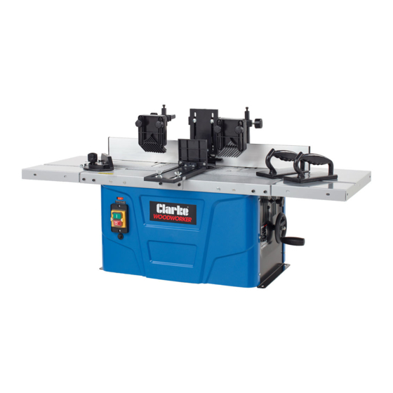
- Page 1 1500W BENCH TOP SHAPER MODEL NO: CBTSR PART NO: 6462079 OPERATION & MAINTENANCE INSTRUCTIONS LS0619 - ISS 1 ORIGINAL INSTRUCTIONS...
-
Page 2: Environmental Protection
INTRODUCTION Thank you for selecting this Clarke Bench Top Shaper. The machine is ideal for shaping wood and plastic and also for cutting out knots, cutting grooves, removing recesses, copying curves and logos, etc. The machine must not be used on metal, stone, etc. -
Page 3: Specifications
SPECIFICATIONS Item Item Specification Operating Voltage and Frequency 230V ~ @ 50 Hz Rated Input Wattage: 1500W Table Size ( with extension) L x W ( mm) 1050 x 360 mm Speeds 11500 rpm to 24000 rpm Spindle height adjustment 0 - 40 mm Max Dimension of workpiece (L x W x H) 650 x 160 x 65 mm... -
Page 4: General Power Tool Safety Warnings
GENERAL POWER TOOL SAFETY WARNINGS WARNING: READ ALL SAFETY WARNINGS AND ALL INSTRUCTIONS. FAILURE TO FOLLOW THE WARNINGS AND INSTRUCTIONS MAY RESULT IN ELECTRIC SHOCK, FIRE AND/OR SERIOUS INJURY. Save all warnings and instructions for future reference. 1. Keep the work area tidy. •... - Page 5 • Tie long hair back in a hair net. 9. Use protective equipment. • Wear protective goggles. • Wear a mask when carrying out dust-creating work. 10. Connect the dust extraction device if you will be processing wood, materials similar to wood, or plastics. •...
- Page 6 15. Pull the plug out of the outlet. • Never remove loose splinters, chips or jammed wood pieces from the running cutter bit. • When the cutter bit is blocked due to abnormal feed force during cutting, turn the machine off. Remove the work piece and ensure that the cutter bit runs freely.
-
Page 7: Additional Safety Instructions
ADDITIONAL SAFETY INSTRUCTIONS 1. Check that the cutters are in perfect condition before use. 2. Use table insert rings appropriate for the size of the cutters. 3. Always wear suitable personal protective equipment. This includes: • Hearing protection to avoid the risk of becoming hearing impaired. •... -
Page 8: Residual Risks
RESIDUAL RISKS The machine is built according to the state of the art and the recognized safety-relevant regulations. Nevertheless individual residual risks can occur during work. • Danger of injury to fingers and hands by the tool due to inappropriate guidance of the work piece. -
Page 9: Electrical Connections
ELECTRICAL CONNECTIONS WARNING! READ THESE ELECTRICAL SAFETY INSTRUCTIONS FULLY BEFORE CONNECTING THE MACHINE TO THE MAINS SUPPLY. This machine is provided with a standard 13 amp, 230 volt (50Hz), BS 1363 plug, for connection to a standard, domestic electrical supply. Should the plug need changing, make sure that a plug of identical specification is used. -
Page 10: Mounting The Machine
ASSEMBLY WARNING: BEFORE CARRYING OUT ANY ADJUSTMENT OR MAINTENANCE, MAKE SURE THAT THE MACHINE IS DISCONNECTED FROM THE MAINS SUPPLY. MOUNTING THE MACHINE It is recommended to fix the machine to a work bench using the four holes provided. 1. Holes must be drilled in the workbench which align with those on the machine base. -
Page 11: Fitting The Fence Plates
2. Drop the sliding bracket over the bolt so that it sits in the grooves on the fence. 3. Secure in place using the washer and plastic cap nut. FITTING THE FENCE PLATES Parts needed for this step Carriage bolt M6 x 25 Plastic cap nut Washers... -
Page 12: Fitting The Downward Pressure Bar
FITTING THE DOWNWARD PRESSURE BAR Parts needed for this step Mounting Bracket Bolt M6 x 40 Washers Pressure Bar Carriage Bolts M6 x 35 Wingnuts 1. Fit the mounting bracket to the central part of the main fence as shown. 2. -
Page 13: Fitting The Pressure Pads
FITTING THE PRESSURE PADS Parts needed for this step Pressure pads Square mounting plate Square supports Clamp Allen screws M6 x 12 Plastic cap screws M6 x 20 Carriage bolts M6 x 35 Plastic cap nuts Washers 1. Insert the 2 square supports in the 2 square sockets on the main part of the fence. - Page 14 3. Slide the square mounting plate into the clamp as shown. 4. Slide the clamp over the square support as shown. 5. Secure in place by tightening the knob on the clamp. 6. Fit the pressure pads to the square mounting plates using 4 carriage bolts, 4 washers and 4 plastic cap nuts.
-
Page 15: Fitting The Moulding Fence Onto The Working Table
FITTING THE MOULDING FENCE ONTO THE WORKING TABLE Parts needed for this step Carriage bolt M6 x 20 Carriage bolt M6 x 40 Plastic cap nuts Washers 1. Fix the 2 plastic cap screws into the grooves in the moulding fence using the washers and carriage bolts as shown. -
Page 16: Fitting The Table Extension
FITTING THE TABLE EXTENSION Parts needed for this step Allen screws M5 x 20 Allen screws M5 x 12 Small Washers Large Washers Hexagonal nuts 14 x Spring washers 1. Attach the extension table to both sides with 4 allen screws M5 x 20, 4 washers, 4 spring washers and 4 hexagonal nuts M5. -
Page 17: Fitting The Kickback Safety Fence
FITTING THE KICKBACK SAFETY FENCE Parts needed for this step Kickback safety fence Mounting bracket Recessed head screws M5 x 10 Washers Spring washers Carriage bolts M6 x 25 Washers Wing nuts 1. Align the mounting bracket with the two holes on the front of the table. -
Page 18: Connection Of A Dust Extractor
CONNECTION OF A DUST EXTRACTOR Slide the suction hose of the dust extractor unit onto the dust extraction port at the rear of the moulding fence. • For hoses with a dia. of 100 mm, an adapter is supplied. FITTING THE TRANSPARENT TOOL GUARD 1. -
Page 19: Before Use
BEFORE USE INSTALLING AND CHANGING THE COLLETS AND CUTTER HEADS WARNING: BEFORE CARRYING OUT ANY ADJUSTMENT OR MAINTENANCE, MAKE SURE THAT THE MACHINE IS DISCONNECTED FROM THE MAINS SUPPLY. 1. Remove the insert rings from the table. 2. Loosen the securing screw and use the handle to raise the spindle to its highest position. - Page 20 4. Loosen the collet nut using the spanner provided and remove the cutter and collet nut if required. 5. Insert the required collet/collet nut and tighten it slightly. 6. Insert the cutter into the collet. • At least 3/4 of the cutter shank must be in the collet before tightening.
-
Page 21: Speed Control
ADJUSTMENTS SPEED CONTROL The speed control has 6 speeds. Determine the optimal setting by testing on a scrap piece of wood. NOTE: The use of the correct setting will increase the life-span of the cutter. It, also affects the quality of the cut. RAISING/LOWERING THE CUTTER To raise or lower the spindle height. -
Page 22: Outfeed Fence Offset
OUTFEED FENCE OFFSET Once the workpiece passes the cutter, it may be thinner then when it started. If so you should adjust the left fence to compensate for the missing material. 1. Loosen the plastic cap screws. 2. Move the left fence towards you slightly and tighten the plastic cap screws. -
Page 23: Using The Machine
USING THE MACHINE 1. Insert an appropriate cutting bit. 2. Adjust the speed, and adjust the fence in such a way that the material is supported along its entire length. 3. Switch the machine on by pressing the green ON (I) button. 4. -
Page 24: Maintenance And Servicing
MAINTENANCE AND SERVICING WARNING: BEFORE CARRYING OUT MAINTENANCE, MAKE SURE THAT THE MACHINE IS DISCONNECTED FROM THE MAINS SUPPLY. CLEANING • Keep all safety devices, air vents and the motor housing free of dirt and dust. Wipe the equipment with a clean cloth or blow it with compressed air at low pressure (always wear PPE when using compressed air). -
Page 25: Declaration Of Conformity
DECLARATION OF CONFORMITY Parts & Service: 020 8988 7400 / E-mail: Parts@clarkeinternational.com or Service@clarkeinternational.com... -
Page 26: Other Items In The Clarke Range
OTHER ITEMS IN THE CLARKE RANGE Parts & Service: 020 8988 7400 / E-mail: Parts@clarkeinternational.com or Service@clarkeinternational.com... - Page 27 OTHER ITEMS IN THE CLARKE RANGE Parts & Service: 020 8988 7400 / E-mail: Parts@clarkeinternational.com or Service@clarkeinternational.com...
Need help?
Do you have a question about the CBTSR and is the answer not in the manual?
Questions and answers