
Related Manuals for Clarke Metalworker CL251MH


Summary of Contents for Clarke Metalworker CL251MH
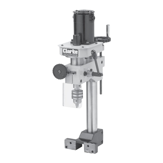
- Page 1 MILLING/DRILLING ATTACHMENT MILLING/DRILLING ATTACHMENT Model No.CL251MH Part No. 7610741 OPERATING & MAINTENANCE OPERATING & MAINTENANCE INSTRUCTIONS INSTRUCTIONS 0803...
-
Page 2: Declaration Of Conformity
SPECIFICATIONS Motor ................230V 50Hz 1ph Power Rating ..............150W Spindle Taper ..............MT2 Spindle Speed ..............10-1300RPM Max. Spindle Travel ............30mm Max. Dist. Chuck to Table ..........168mm Dist. Column to Chuck Centre ........105mm Overall Dimensions (WxDxH) .......... 220x410x575mm Weight net ............... -
Page 3: Table Of Contents
Thank you for purchasing this CLARKE - Micro Milling and Drilling machine attachment, designed for use with model CL250M Variable Speed Metal Lathe Before attempting to operate the machine, please read this instruction manual thoroughly, and follow all directions carefully. By doing so you will ensure the safety of both yourself and others around you, and at the same time, you should look forward to the Press giving you long and trouble free service. -
Page 4: Safety Precautions
GENERAL SAFETY PRECAUTIONS FOR OPERATING MACHINERY WARNING As with all machinery, there are certain hazards involved with their operation and use. Exercising respect and caution will considerably lessen the risk of personal injury. However, if normal safety precautions are overlooked, or ignored, personal injury to the operator, or damage to property may result. -
Page 5: Additional Safety Rules For Mill/Drills
19. DO NOT STAND ON THE MACHINE. Serious injury could occur if the machine is tipped over. Do not store materials above or near the machine such that it is necessary to stand on the machine to get to them. 20. -
Page 6: Electrical Connections
Please note that the wires in the mains lead are coloured in accordance with the following code; Green & Yellow Earth Blue Neutral Brown Live WARNING! DO NOT attempt to fit a replacement cable unless you are fully familiar with electrical systems. Consult a qualified technician, or your nearest Clarke dealer. -
Page 7: Preparation For Use
Mounting Bolts w/washers Check the parts off against the above list. Should there be any deficiencies or damage, you should contact your CLARKE dealer immediately . Remove all traces of preservative from the Mill/Drill with a good quality solvent, and wipe all parts thoroughly with a clean dry cloth. -
Page 8: Assembly
ASSEMBLY Ensure the power supply to the lathe is disconnected. If any accessories are attached to the cross slide of the lathe, they must be removed before fitting the Mill/Drill Head. Slacken the Tailstock securing bolts and slide it to the end of the bed and secure in this position. -
Page 9: Operation
Similarly, a means of holding and securing a Mill or Drill bit is required. A Collet set and a Mill Chuck set are available for this purpose, from your Clarke dealer. A set of End Mills is also available with sizes ranging from 3 -10mm. - Page 10 2. Lower the Head complete, using Handwheel ‘A’, until the Mill is a few millimetres from the workpiece. 3. Turn the handwheel ‘B’ clockwise until the Mill just comes into contact with the workpiece, then very carefully zero the scale by holding the handwheel steady and turning the scale independently so that the ‘0’...
-
Page 11: Maintenance
Drill Press is properly maintained. Always inspect before use. Any damage should be repaired, and maladjustments rectified. If you are unable to rectify any faults, please contact your local dealer or Clarke International Service Division on 020 8556 4443 for assistance. -
Page 12: Accessories
ACCESSORIES The following accessories are available from your dealer. When ordering, please quote the part number shown. 1. Quick Vise With jaws 50mm wide, maximum opening of 37mm and 15mm deep. ‘T’ bolts with nuts and washers are provided for mounting to the CL250M Lathe cross slide. -
Page 13: Spare Parts And Service Contacts
SPARE PARTS & SERVICING For Spare Parts or Servicing, please contact your nearest dealer, or CLARKE International, on one of the following numbers. PARTS - 020 8558 6696 : SERVICE - 020 8556 4443 PARTS & SERVICE FAX - 020 8 558 3622 PARTS E-MAIL - Parts@clarkeinternational.com... -
Page 14: Parts Lists And Diagrams
PARTS LIST No: Description Qty Part No: No: Description Qty Part No: 177 Connect shaft SG251MH177 133 Handle bolt SG251MH133 178 Pin 3*18 SG251MH178 134 Handle sleeve SG251MH134 179 Worm shaft SG251MH179 135 Handwheel SG251MH135 180 Dial SG251MH180 136 Leadscrew bkt SG251MH136 181 Lock bolt SG251MH181... - Page 15 PARTS DIAGRAM...
Need help?
Do you have a question about the Metalworker CL251MH and is the answer not in the manual?
Questions and answers