
Subscribe to Our Youtube Channel
Related Manuals for Clarke Strong-Arm CSA20F


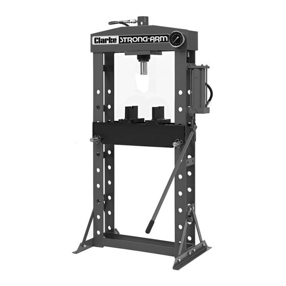
Summary of Contents for Clarke Strong-Arm CSA20F
- Page 1 WARNING: Read these instructions before using the machine 20 TONNE HYDRAULIC PRESS MODEL NO: CSA20F PART NO: 7614055 OPERATION & MAINTENANCE INSTRUCTIONS GC0913...
- Page 2 GUARANTEE This CLARKE product is guaranteed against faulty manufacture for a period of 12 months from the date of purchase. Please keep your receipt as proof of purchase.
-
Page 3: Safety Precautions
SAFETY PRECAUTIONS 1. During assembly or if the press is moved, always call for the help of an assistant, do not manhandle single-handedly. 2. Ensure the press is bolted down onto a solid, flat surface. 3. Ensure the press is located on firm level ground with adequate light. 4. -
Page 4: Tools Required
UNPACKING Ensure the press and its components suffered no damage during transit and that all components are present. Should any loss or damage become apparent, please contact your CLARKE dealer immediately INVENTORY • 1 x Frame • 2 x Base Supports •... - Page 5 ASSEMBLY IMPORTANT: Due to the weight of the press components, we recommend that you get assistance during assembly. IMPORTANT: We strongly recommend that the press be firmly secured to a firm and level floor using expansion bolts (not supplied). Holes are provided in the base supports for this purpose.
- Page 6 7. Fit the pressure gauge to the connecting nut, sealing the thread with PTFE tape.Check the gauge is upright before tightening the nut with a 19 mm spanner. 8. Make a small hole in the pressure gauge safety bung with a short pin or nail before use.
-
Page 7: Adding A Mandrel Set
ADDING A MANDREL SET A mandrel set (including storage bracket and pressure plate) is not supplied with the press but is available as Clarke part no 7615062. 1. Bolt the mandrel storage bracket to the side of the frame using the bolts supplied. -
Page 8: Preparation For Use
PREPARATION FOR USE 1. Insert the pump handle into the pump actuating lever. 2. Purge any air from the system by opening the release valve (turning the control knob anti- clockwise) and pumping several full strokes to eliminate any air bubbles. -
Page 9: Fitting The Mandrels
FITTING THE MANDRELS If a set of mandrels is available, any one may be connected to the end of the ram using the adaptor supplied. Alternatively, the basic pressure cap can be fitted as shown. Secure the pressure cap by tightening the grub screw with a suitable hexagonal key. -
Page 10: Operation
OPERATION 1. Place the workpiece on the bed. It must be completely stable and supported by packing or shims where required. Steel pressing plates are supplied, which locate on the bed. Place the workpiece on a combination of these to give it stability. CAUTION: DO NOT POINT LOAD THESE ACCESSORIES AS THEY ARE NOT DESIGNED TO TAKE THE FULL FORCE OF THE RAM IN ONE SPOT. -
Page 11: Maintenance
Oil should be level with the bottom of the hole. If necessary top up with CLARKE hydraulic oil, Part No. 3050830. This task is carried out with the ram fully retracted. -
Page 12: Troubleshooting
TROUBLESHOOTING Problem Probable Cause Remedy Pump unit will not work Dirt on valve seat/warn Bleed pump unit or have seals unit overhauled with new seals Pump will not produce Air-lock Open the release valve pressure and remove the oil filler Pump feels hesitant plug. -
Page 13: Technical Specifications
TECHNICAL SPECIFICATIONS Capacity 20 Tonne Operating Pressure 69 Mpa Bursting Pressure 138 Mpa Ram Travel 189 mm Ram Shaft Diameter 76 mm Net Weight 138 kg Dimensions D x W x H 560 x 800 (exc pump) x 1610 Throat Width 550 mm Throat Depth (Ram to pressing plate) Platform at highest;- 30 mm... -
Page 14: Frame Assembly Parts Diagram
FRAME ASSEMBLY PARTS DIAGRAM Parts & Service: 020 8988 7400 / E-mail: Parts@clarkeinternational.com or Service@clarkeinternational.com... -
Page 15: Frame Assembly Parts List
Roller Shaft Spring Clip Axle Bolt Bed Blocks Bearing Assembly Ram Base Plate Ram Assembly Bolt M10 x 25 MANDREL SET (CLARKE PART NO 7615062) PART NO DESCRIPTION PART NO DESCRIPTION Mandrel/Adaptor Bracket 25mm Mandrel 10mm Mandrel 30mm Mandrel 12mm Mandrel... -
Page 16: Ram Parts Diagram
RAM PARTS DIAGRAM PART NO DESCRIPTION PART NO DESCRIPTION Dust Cap Protective End Cap Coupling Bolt Bolt M8 x 40 Cylinder Screw Cylinder Piston Ring Seat of Cylinder Piston Cap Locking Collar O-ring Nut M6 O-ring Spring O-ring End Pressure Cap Rectangular Ring Bolt M6 x 7 Protective Ring... -
Page 17: Pump Parts Diagram
PUMP PARTS DIAGRAM PART NO DESCRIPTION PART NO DESCRIPTION Steel Ball End Plate End Block Assembly O-Ring Lever Assembly Side Plug Bolt Cylinder Spring Tie Rod O-Ring Plug Steel Ball Washer Valve End Piston Spring End Cap Washer Seal Valve Body O-Ring Piston Rod Control Knob... -
Page 18: Declaration Of Conformity
DECLARATION OF CONFORMITY Parts & Service: 020 8988 7400 / E-mail: Parts@clarkeinternational.com or Service@clarkeinternational.com... - Page 19 NOTES _____________________________________________________________________________ _____________________________________________________________________________ _____________________________________________________________________________ _____________________________________________________________________________ _____________________________________________________________________________ _____________________________________________________________________________ _____________________________________________________________________________ _____________________________________________________________________________ _____________________________________________________________________________ _____________________________________________________________________________ _____________________________________________________________________________ _____________________________________________________________________________ _____________________________________________________________________________ _____________________________________________________________________________ Parts & Service: 020 8988 7400 / E-mail: Parts@clarkeinternational.com or Service@clarkeinternational.com...
Need help?
Do you have a question about the Strong-Arm CSA20F and is the answer not in the manual?
Questions and answers