
Subscribe to Our Youtube Channel
Related Manuals for Clarke CBM 2


Summary of Contents for Clarke CBM 2
- Page 1 MORTISING MACHINE Model No. CBM 2 Part No. 6500010 OPERATING & MAINTENANCE INSTRUCTIONS...
-
Page 2: Table Of Contents
GUARANTEE This CLARKE product is guaranteed against faulty manufacture for a period of 12 months from the date of purchase. Please keep your receipt as proof of purchase. This guarantee is invalid if the product is found to have been abused or tampered with in any way, or not used for the purpose for which it was intended. - Page 3 CHECK for DAMAGE. Before using the machine, any damaged part, such as a guard etc., should be checked to ensure that it will operate properly, and perform its intended function. Check for alignment of moving parts, breakage of parts, mountings, and any other condition that may affect the machines’...
-
Page 4: Additional Precautions For Mortising Machines
22. HANDLE WITH EXTREME CARE Whenever transporting or installing machinery, and always use a lifting tool wherever possible. 23. AVOID ACCIDENTAL STARTING. Ensure the switch is OFF before plugging in to mains. 24. BE AWARE that accidents are caused by carelessness due to familiarity. ALWAYS concentrate on the job in hand, no matter how trivial it may seem. -
Page 5: Electrical Connections
ELECTRICAL CONNECTIONS Connect the mains lead to a standard, 230 Volt (50Hz) electrical supply through an approved 13 amp BS 1363 plug, or a suitably fused isolator switch. WARNING! THIS APPLIANCE MUST BE EARTHED IMPORTANT: The wires in the mains lead are coloured in accordance with the following code Green &... -
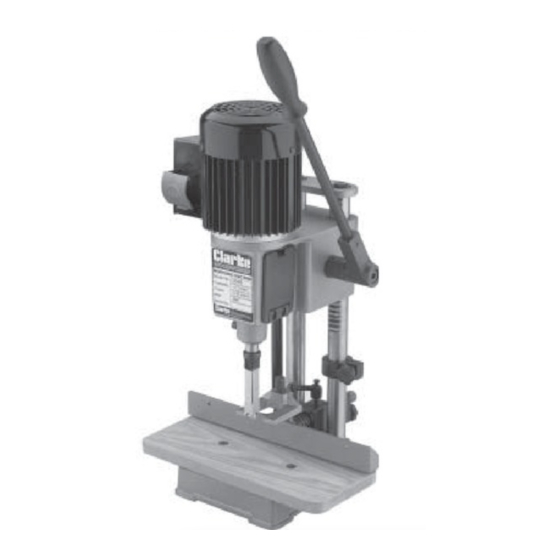
Page 6: Unpacking & Principal Parts
UNPACKING Unpack the shipping carton, and lay out the components so that they can be clearly identified. Fig. 1 Check them off as follows: A. Morticing Machine B. Hydraulic Cylinder D. Handle E. 3/4” Chisel Bush F. 5/8” Chisel Bush G. -
Page 7: Mounting The Chisel & Bit
Assemble the Table to the base using the two screws provided. Insert the bar of the Fence assembly through the hole in the column and secure with the Fence Locking Handle. Assemble the ‘Hold Down’ on the vertical post of the fence assembly, and secure with the set screw, using the Allen Key provided. -
Page 8: Installation
NOTE: The screw should not become tight at this point. If it does, loosen it and retry, making certain that the round hole in the side of the bush is lined up with the screw. Insert the bit into the chisel, and insert chisel and bit up through the bush. NOTE: The opening in the side of the chisel should always be to the right or left, never to the front or rear. - Page 9 ADJUSTING HOLD DOWN The purpose of the hold down in to prevent the workpiece from lifting as the chisel is raised up, out of the hole. The hold down should be adjusted so it just touches the top of the workpiece and allows the workpiece to slide left or right.
-
Page 10: Operation
Fig. 9 OPERATION Position the motor assembly at a suitable height on the column according to the depth of the workpiece. Set the machine fence to suit the position of the mortise on the workpiece. Make sure the fence and chisel are square to each other, and tighten in place. Set the depth stop to the required depth of cut. -
Page 11: Maintenance
in hollow chisel mortising and is caused by material chip friction and the resins in the stock being burned off. Bluing of the chisel after initial use is not indicative of a dull chisel, but a combination of friction and resin buildup on the cutting faces of the chisel. A dull chisel can be detected by the amount of excess force required to complete a cut. -
Page 12: Specifications
SHARPENING THE DRILL BIT & CHISEL For best performance the chisel and bit need to be kept sharp. Blunt cutting edges will give untidy and inaccurate mortises, and can cause overheating and breaking of the chisel and bit. Fig. 12 Sharpen the bit by using a small smooth file, following the original shape of the bit. -
Page 13: Parts List & Accessories
Cylinder Head FMHM120S24 Screw FMHM120S49 ACCESSORIES In addition to the 13mm (1/2”) Hardened Steel, Hollow Mortise Chisel supplied with your machine, the following sizes are available from your CLARKE dealer. Mortise Size Bit Shank Size Part No. 6mm (1/4”) 6500025 9mm (3/8”) -
Page 14: Parts Diagram
PARTS DIAGRAM...
Need help?
Do you have a question about the CBM 2 and is the answer not in the manual?
Questions and answers