
Related Manuals for Clarke CDP10B


Summary of Contents for Clarke CDP10B
-
Page 1: Drill Press
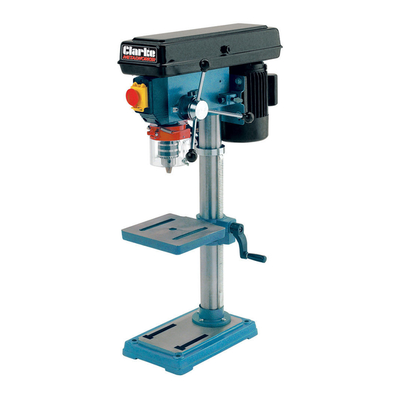
DRILL PRESS MODEL NO: CDP10B PART NO: 6550020 OPERATION & MAINTENANCE INSTRUCTIONS GC0514... -
Page 2: Environmental Protection
INTRODUCTION Thank you for purchasing this CLARKE Drill Press. Before attempting to use this product, please read this manual thoroughly and follow the instructions carefully. In doing so you will ensure the safety of yourself and that of others around you, and you can look forward to your purchase giving you long and satisfactory service. -
Page 3: General Safety Rules
GENERAL SAFETY RULES WARNING: WHEN USING ELECTRIC TOOLS, BASIC SAFETY PRECAUTIONS SHOULD ALWAYS BE FOLLOWED TO REDUCE THE RISK OF FIRE, ELECTRIC SHOCK AND PERSONAL INJURY INCLUDING THE FOLLOWING. READ ALL THESE INSTRUCTIONS BEFORE ATTEMPTING TO OPERATE THIS PRODUCT AND SAVE THESE INSTRUCTIONS FOR FUTURE REFERENCE. GENERAL SAFETY IN THE WORKPLACE 1. -
Page 4: Additional Safety Rules For Drill Presses
5. Always disconnect the machine from the power supply before carrying out any servicing or changing of accessories. 6. Before further use of the tool, it should be carefully checked to determine that it will operate properly and perform its intended function. Check for alignment of moving parts, binding of moving parts, breakage of parts, mounting or other condition that may affect its operation. -
Page 5: Protective Clothing
3. Always use clamps or a drill vice bolted to the table, to hold the work. It should never be held with bare hands. 4. Always shut off the power & remove drill bit before leaving the machine. 5. Always make all adjustments with the power off. 6. -
Page 6: Electrical Connections
ELECTRICAL CONNECTIONS WARNING! Read these electrical safety instructions thoroughly before connecting the product to the mains supply. Before switching the product on, make sure that the voltage of your electricity supply is the same as that indicated on the rating plate. This product is designed to operate on 230VAC 50Hz. -
Page 7: Parts Inventory
PARTS INVENTORY Head Assembly Chuck Key Column c/w Rack Chuck Guard Assembly Base Drift Wedge Table Crank Handle Worm Drive Bolts M10 x 25 Arbor Hex Keys Chuck Feed Handles (x 3) Parts & Service: 020 8988 7400 / E-mail: Parts@clarkeinternational.com or Service@clarkeinternational.com... -
Page 8: Column To Base
The drill press is delivered with the components shown on page 7. Check the parts against the list. Should there be any deficiencies or damage, you should contact your CLARKE dealer immediately where the product was originally purchased. Do not discard the packaging until the machine is assembled. -
Page 9: Head To Column
3. Slacken the grub screw securing the collar to the column and pull collar and rack off the column. 4. Slide the rack through the slot in the table support with the long, smooth end uppermost, so that the rack teeth engage with the worm, as shown in Fig 2, and holding in this position, slide the table support, with rack, onto the... -
Page 10: Chuck Guard Assembly
3. Locate the three feed handles, and screw them firmly into the hub of the feed shaft as shown in Fig.5. CHUCK GUARD ASSEMBLY NOTE: This task should be carried out before the chuck is installed. 1. Assemble the transparent guard to the guard support using the small bolt/nut and the two small screws provided. -
Page 11: Removing The Chuck
REMOVING THE CHUCK 1. Turn the lower feed handles to lower the chuck to its lowest position. 2. Insert a tapered drift key into the corresponding slot in the quill assembly and tap sharply with a mallet to release the tapered chuck arbor. -
Page 12: Settings And Adjustments
SETTINGS AND ADJUSTMENTS TABLE The table may be raised, lowered or swivelled about the column, by slackening off the table support locking handle, adjusting the table position accordingly and re- tightening the handle. It may also be tilted by loosening the screw which secures the table to its mount beneath the table, tilting the table to the required position and... -
Page 13: Spindle Depth Stop
SPINDLE DEPTH STOP Located around the spindle feed shaft is a depth stop collar carrying a graduated scale (A, Fig.13). The collar is capable of turning about the shaft and may be locked in place by locking screw B. The graduations are metric (mm). -
Page 14: Drill Operating Speeds
DRILL OPERATING SPEEDS The table below gives the belt arrangement for given drill speeds. A similar chart is also located on the inside of the pulley cover. The diagram shows the belts fitted to step 4 of the spindle pulley and step 1 of the motor pulley, giving a speed of 210rpm. -
Page 15: Operation
OPERATION 1. Insert the drill into the jaws of the chuck by approx 1", ensuring that the jaws do not touch the flutes of the drill. Before tightening the chuck, ensure that the drill is centred within the jaws. 2. Ensure the table height and position is set, so that drill travel is sufficient for the job in hand. - Page 16 Form the habit of checking to see that the chuck key is removed from the machine before turning it on. A micro switch is provided within the pulley cover, which prevents the machine from operating unless the pulley cover is fully closed. Parts &...
-
Page 17: Cutting Speeds
DRILL PRESS VICES In order to secure the workpiece to the table, a complete range of Drill Press vices, Cross Vices and Clamps, is available from your Clarke dealer. Parts & Service: 020 8988 7400 / E-mail: Parts@clarkeinternational.com or Service@clarkeinternational.com... -
Page 18: Maintenance
Please refer to the trouble shooting chart on page 19. If you are unable to rectify any faults, please contact your local dealer or Clarke International for assistance. MONTHLY (IF IN CONSTANT USE) 1. -
Page 19: Troubleshooting
Close pulley cover. g. Micro switch on cover g. Check operation of micro not operating. switch, and renew/adjust as necessary. (Consult your Clarke dealer for advice). Drill binds in work- a. Excessive feed a. Apply less pressure. piece. pressure. -
Page 20: Suitable Accessories
Table difficult to a. Needs lubrication. a. Lubricate with light oil. raise. b. Table lock tightened. b. Loosen clamp. SUITABLE ACCESSORIES Drill Press Vices available from your Clarke dealer include: Model Jaw Width Max Opening Depth Weight Part No CDV30C... -
Page 21: Specification
SPECIFICATION Overall Height 840 mm Column to Chuck Centre 127 mm Table Dimensions 200 x 200 mm Base Dimensions 210 x 340 mm Column Dia 60 mm Chuck Capacity 16 mm Max Chuck to Table Distance 350 mm Max Chuck to Base Distance 465 mm Spindle Speed Range 210 - 2580 rpm... -
Page 22: Component Parts - Pulley Assembly
COMPONENT PARTS - PULLEY ASSEMBLY No Description No Description Belt Pulley Cover Bearing Circlip Idler Pulley Bearing Idler Shaft Spacer Motor Pulley Shaft Grub Screw Pulley Screw Securing Screw Cable Clamp Cover Knob Grommet Circlip Screw Circlip All items please ref: QBCDP10BP01-22 Parts &... -
Page 23: Component Parts - Base Assembly
COMPONENT PARTS - BASE ASSEMBLY No Description No Description Grubscrew Column Rack Collar Bolt M8 Pinion Table Tilt Bolt Handle Assembly Rack Square Table Table Trunnion Clamp Worm Base Pinion Pin All items please ref: QBCDP10BB01 onwards Parts & Service: 020 8988 7400 / E-mail: Parts@clarkeinternational.com or Service@clarkeinternational.com... -
Page 24: Component Parts -Head Assembly
COMPONENT PARTS -HEAD ASSEMBLY No Description No Description Locking Screw Spring Cover/Adjuster Grub Screw Collar Head Assembly Shaft Allen Key Screw Allen Key Knob Cable Assembly Handle Adjuster Bar Washer Bolt Screw Washer Plastic Cover Motor Adjuster Plate Switch Assembly Motor Cable Screw Motor Assembly... -
Page 25: Component Parts - Quill Assembly
COMPONENT PARTS - QUILL ASSEMBLY No Description No Description Lock Nut Chuck Guard Assembly Flat Washer Bearing Bearing Spindle O-Ring Arbor Quill Shaft Chuck Wedge Drift Chuck Key When ordering spare parts, please quote the reference QBCDP10QB01 onwards. Parts & Service: 020 8988 7400 / E-mail: Parts@clarkeinternational.com or Service@clarkeinternational.com... -
Page 26: Declaration Of Conformity
DECLARATION OF CONFORMITY Parts & Service: 020 8988 7400 / E-mail: Parts@clarkeinternational.com or Service@clarkeinternational.com... - Page 27 NOTES _____________________________________________________________________________ _____________________________________________________________________________ _____________________________________________________________________________ _____________________________________________________________________________ _____________________________________________________________________________ _____________________________________________________________________________ _____________________________________________________________________________ _____________________________________________________________________________ _____________________________________________________________________________ _____________________________________________________________________________ _____________________________________________________________________________ _____________________________________________________________________________ _____________________________________________________________________________ _____________________________________________________________________________ Parts & Service: 020 8988 7400 / E-mail: Parts@clarkeinternational.com or Service@clarkeinternational.com...
Need help?
Do you have a question about the CDP10B and is the answer not in the manual?
Questions and answers