
Related Manuals for Clarke CBM 2B


Summary of Contents for Clarke CBM 2B
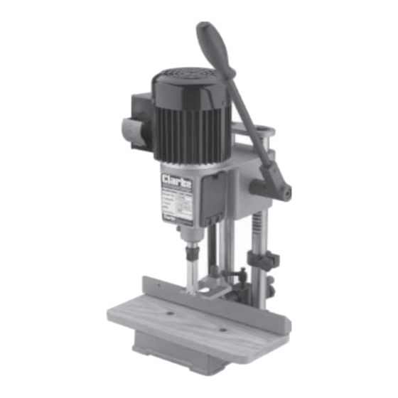
- Page 1 MORTISING MACHINE Model No. CBM 2B Part No. 6500005 OPERATING & MAINTENANCE INSTRUCTIONS 0202...
- Page 2 PARTS & SERVICE PARTS & SERVICE TEL: 020 8988 7400 e-mail as follows: PARTS: Parts@clarkeinternational.com SERVICE: Service@clarkeinternational.com © Copyright CLARKE International. All rights reserved. February,2002...
-
Page 3: Table Of Contents
GUARANTEE This CLARKE product is guaranteed against faulty manufacture for a period of 12 months from the date of purchase. Please keep your receipt as proof of purchase. This guarantee is invalid if the product is found to have been abused or tampered with in any way, or not used for the purpose for which it was intended. -
Page 4: Safety Precautions
SAFETY PRECAUTIONS GENERAL SAFETY RULES FOR OPERATING MACHINERY WARNING: As with all machinery, there are certain hazards involved with their operation and use. Exercising respect and caution will considerably lessen the risk of personal injury. However, if normal safety precautions are overlooked or ignored, personal injury to the operator or damage to property, may result. -
Page 5: Additional Precautions For Mortising Machines
14. KEEP CHILDREN AWAY. All visitors should be kept a safe distance from the work area, especially whilst operating the unit. 15. MAINTAIN MACHINE IN TOP CONDITION. Keep tools sharp and clean for the best and safest performance. Follow maintenance instructions. 16. -
Page 6: Electrical Connections
ELECTRICAL CONNECTIONS Connect the mains lead to a standard, 230 Volt (50Hz) electrical supply through an approved 13 amp BS 1363 plug, or a suitably fused isolator switch. WARNING! THIS APPLIANCE MUST BE EARTHED IMPORTANT: The wires in the mains lead are coloured in accordance with the following code Green &... -
Page 7: Unpacking & Principal Parts
Unpack the shipping carton, and lay out the components so that they can be clearly identified. Check them off as follows: Should there be any deficiency or damage to any of the components, please contact your Clarke dealer immediately Chuck Key 1. Operating Handle c/w pin & spring 2 x Hex. -
Page 8: Assembly
ASSEMBLY. WARNING: For your own safety, do not connect the Mortising Machine to a power source until it is fully assembled, and you have read and understood all safety and operational instructions. Secure the Operating Handle by screwing the pin with spring into the hole in the pinion shaft. - Page 9 Assemble the Table to the base using the two countersunk headed screws provided. Insert the stem of the Fence assembly through the hole in the block and secure with the Fence Locking Lever. First screw the post into the housing..5A..then attach the Locking Lever and secure with the screw and spring.
-
Page 10: Mounting The Chisel & Bit
Lower the Hold Down on to the post, and secure temporarily, by tightening the grub screw. Slacken the Fence Locking Lever then push the Fence IN fully so that the Fence Adjuster may be positioned on the Fence stem as shown. - Page 11 PREPARING FOR USE WARNING: Make sure the machine is disconnected from the mains supply before performing checks, adjustments, or setup procedures. INSTALLING CHISEL AND BIT CAUTION! The chisel and drill bit are extremely sharp...take care when handling! Open the cover...at either side, by pulling down on the plastic catch,to expose the chuck.
-
Page 12: Controls And Adjustments
11. Push the drill bit up through chisel, and into the opened jaws of the chuck as far as it will go, then back off approx. 1/16”(2mm). Secure the drill bit in this position, by tightening the jaws using the chuck key provided. Note: It is important that the drill bit bottoms out on... - Page 13 ADJUSTING CHISEL PARALLEL TO WORKPIECE It is important that the chisel is square to the workpiece. To achieve this, slacken the chisel securing screw and rotating the chisel until the back surface is flat against the workpiece, or a piece of wood with parallel sides, resting against the fence, then re-tighten the screw, ensuring a distance of...
-
Page 14: Operation
OPERATION Set the fence to suit the position of the mortise on the workpiece. Make sure the fence and chisel are square to each other (see p13), and tighten in place. Make any fine adjustments to the fence, to move the workpiece in or out, by using the adjuster at the rear of the fence (see p12). -
Page 15: Maintenance
• Do not have the slot against the blind end of the mortise, as the chips will not be able to clear from the chisel. This will cause overheating and possible breakage to the chisel or bit. • When cutting deep mortises, make the cut in several stages of approximately 25mm each, to allow chips to clear. -
Page 16: Sharpening Drill Bit & Chisel
SHARPENING THE DRILL BIT & CHISEL For best performance the chisel and bit need to be kept sharp. Blunt cutting edges will give untidy and inaccurate mortises, and can cause overheating and breaking of the chisel and bit. Sharpen the bit by using a small smooth file, following the original shape of the bit. -
Page 17: Parts List & Diagram
SPARE PARTS PARTS LIST No. Description Qty Part No. No. Description Qty Part No. 11 Hex. Key 4mm 1 EFCBM2B11 1 Fence 1 EFCBM2B01 12 Chuck Key 1 EFCBM2B12 2 Hold Down 1 EFCBM2B02 13 Damper 1 EFCBM2B13 3 Hold Down Post 1 EFCBM2B03 14 Operating Lever 1 EFCBM2B14... -
Page 18: Accessories
ACCESSORIES The following Morticing Chisels and Bits are available from your CLARKE dealer. Mortice Width Bit Shank Size Part No. 6mm (1/4”) ....5mm ........6500025 9mm (3/8”) ....6mm ........6500026 3. 13mm (1/2”) ....9mm ........6500027 4. 16mm (5/8”) ....13mm ......... 6500028 SPECIFICATIONS Motor ..............
Need help?
Do you have a question about the CBM 2B and is the answer not in the manual?
Questions and answers