Table of Contents
Advertisement
Quick Links
Download this manual
See also:
Instruction Manual
Advertisement
Table of Contents

Subscribe to Our Youtube Channel
Related Manuals for National Flooring Equipment 5280 Series


Summary of Contents for National Flooring Equipment 5280 Series
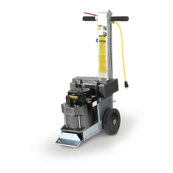
- Page 1 5280 SELF-PROPELLED SCRAPER SERVICE MANUAL Read Manual Before Servicing Machine 402972 Rev D...
-
Page 3: Table Of Contents
Table of Contents Table of Contents ........................................3 ......................................... 4 Troubleshooting Guide ......................................8 Maintenance ..........................................9 Wheel Removal ......................................9 Adding/Changing Hydraulic Fluid ................................. 9 Inspection of Internal Parts ................................... 9 Tank Removal ....................................... 9 Control Valve Replacement ..................................10 Speed Control Replacement.................................. - Page 4 Forward Hydraulic Handle Control Speed Control Dial Saddle Weight Lifting Bail Eyebolts Weight Vibration Width Length Height Weight Speed Amps X Axis Y Axis Z Axis 17” 27” 39” 263 lbs 3.1-12.7 Under 6.7 1,725 7.8 m/s 12.1 m/s 14.5 m/s m/min (full load) (119.3 kg)
- Page 5 Read the manual carefully to learn equipment applications and limitations, as well as potential hazards associated with this type of equipment. Keep manual near machine at all times. If your manual is lost or damaged, contact National Flooring Equipment (NFE) for a replacement. Personal Maintenance &...
- Page 6 Safety Safety WALK-BEHIND SCRAPER SAFETY GUIDELINES Before use, anyone operating this equipment must read and understand these safety instructions. Scraping Beware of hidden obtrusions. use on largely uneven surfaces. Observe location of electrical supplies and extension cords. Do not allow cutting heads to come into contact with any electrical supply or extension cord.
- Page 7 Safety HYDRAULIC SAFETY Maintaining a Safe Work Environment Establishing a safe work environment in and around your hydraulic equipment is extremely important. The easiest and most effective way to avoid problems is to make sure associates understand their equipment, know how to operate the machines safely, and recognize the dangers if handled carelessly.
-
Page 8: Troubleshooting Guide
Troubleshooting Guide Problem Cause Solution No forward movement. Damaged belt. Remove front cover plate and inspect belt. Damaged speed control valve. Inspect speed control valve. Turn counter-clockwise to open valve. Motor shuts off or won’t start. Inspect capacitor or start switch. -
Page 9: Maintenance
Maintenance WARNING: ALWAYS UNPLUG MACHINE BEFORE PERFORMING MAINTE- NANCE. WHEEL REMOVAL Unplug machine; lay it on its side. Use 5 mm Hex wrench to remove wheel securing screw (Figure 8). FIG. 8 Remove wheel securing cap; wheel will slide off. Watch for keyway key. Remove wheel spacer. -
Page 10: Control Valve Replacement
Maintenance CONTROL VALVE REPLACEMENT Disconnect valve plunger from control linkage. Mark the placement of the four hoses so they can be returned to their original positions. Disconnect and remove the four hoses from valve body. Remove valve mounting bolts and nuts, remove valve. Reverse these steps for installation. -
Page 11: Parts List And Diagrams
Parts List and Diagrams EXTERNAL 13 & 5 PART# DESCRIPTION PART# DESCRIPTION 1 400330 WHEEL, DRIVE, LIGHT DUTY, COMPLETE 2 10 73228 EYE BOLT, 3/8-16 X 8 2 5280-136 COVER, BLADE 11 6280-404 HOLDER, BLADE WRENCH 3 5280-137W WRENCH, BLADE 12 6280-161B PLUG, VENT, FILLER CAP 4 5280-138... -
Page 12: Pump
Parts List and Diagrams PUMP PART# DESCRIPTION PART# DESCRIPTION 1 5280-1 CHAIN, DRIVE, 40 STRAND 13 5280-118 FITTING, 90 DEGREE 2 5280-1L LINK, MASTER 14 5280-129 ECCENTRIC 3 5280-2 SPROCKET, 40BS13 3/4 15 5280-132C PULLEY, PUMP 4 5280-3 SPROCKET, MOTOR, 40BS12X1 16 73903 KEY, 3/16X3/16X2-1/4 5 5280-4... -
Page 13: Handle
Parts List and Diagrams HANDLE PART# DESCRIPTION PART# DESCRIPTION 1 6280-117 FITTING, PUMP 16 5700-76 HOSE, HYDRAULIC, 3/8 X 26, F/F 2 5280-167 HANDLE BODY 17 6280-207 SWITCH, ON-OFF 3 5280-167B COVER, HANDLE BODY 18 6280-215 VALVE BLOCK ASSEMBLY 4 5280-167C PLATE, HANDLE SWITCH 19 73002 WASHER, SPLIT LOCK 1/4... -
Page 14: Back Of Machine
Parts List and Diagrams BACK OF MACHINE PART# DESCRIPTION PART# DESCRIPTION 1 5280-139C ISOLATOR, HANDLE VIBRATION 5 73502 STRAIN RELIEF, STRAIGHT 1/2 INCH, .3376- 2 6280-168 CORD, POWER, NEW STYLE (DOMESTIC .5686 ONLY) 6 401438 PLUG, MALE, EU1-16P, 250V, 16A, EUROPE 72612 ASSEMBLY, 120V HANDLE CORD (INTERNATIONAL ONLY, EXCLUDING... -
Page 15: Hydraulic Tank
Parts List and Diagrams PART# DESCRIPTION HYDRAULIC TANK 1 5280-120 HOSE, HYDRAULIC, 3/8 X 9.25, 90F/90F 2 5280-162-SV HYDRAULIC TANK BODY, SILVER VEIN 3 6280-214 PLUG, TANK 4 6280-161D HYDRAULIC TANK FILLER CAP 5 6280-162G MAGNET, TANK (NOT SHOWN) 6 70601 STRAINER, TANK MOUNTED 7 72816 FITTING, ELBOW, 90 DEGREE, 3/8”... - Page 16 Parts List and Diagrams HANDLE (INTERNATIONAL ONLY) ITEM NO. PART NUMBER DESCRIPTION QTY. 74630 Bolt, Hex Head Cap M6-12 8.8 403806 Plate, Handle, Top 403795 Cover, Handle Body, CE 403817 Switch, Safety, 230V, 50Hz 401438 Plug, Male, EU1-16P, 250V, 16A, Europe 403797 Screw, Phillips Pan Head, M5-0.8 x 50mm...
-
Page 17: Wiring
Parts List and Diagrams WIRING 5280 MACHINE WIRING 5280 MACHINE WIRING 220V 110V BROWN BLACK BLUE WHITE PLUG PLUG ON/OFF ON/OFF SWITCH SWITCH GREEN/YELLOW GREEN FEMALE FEMALE PLUG PLUG MALE MALE PLUG PLUG MOTOR MOTOR... -
Page 18: Hydraulics
Parts List and Diagrams HYDRAULICS... -
Page 19: Warranty
Warranty National Flooring Equipment Inc. (referred to as “the Company”) warrants that each new unit manufactured by The Company, to be free from defects in material and workmanship in normal use and service for a period of twelve (12) months from date of shipment from the Company. For furnished and installed on the product by the Company but manufactured by others, including but not limited to: engines, motors, electrical com- ponents, transmissions etc., shall carry the accessory manufacturers own warranty. - Page 20 9250 Xylon Avenue N • Minneapolis, MN 55445 • U.S.A. Toll-free 800-245-0267 • Phone 763-315-5300 • Fax 800-648-7124 • Fax 763-535-8255 Web Site: www.nationalequipment.com • E-Mail: info@nationalequipment.com...
Need help?
Do you have a question about the 5280 Series and is the answer not in the manual?
Questions and answers