
Related Manuals for National Flooring Equipment 7700


Summary of Contents for National Flooring Equipment 7700
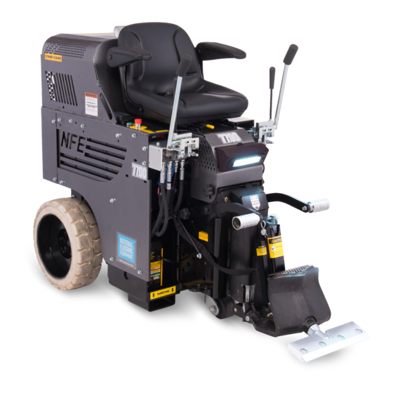
- Page 1 7700 ALL-DAY BATTERY RIDE-ON SCRAPER SERVICE MANUAL Read Manual Before Servicing Machine 402971 Rev H...
-
Page 3: Table Of Contents
Table of Contents Table of Contents ................................3 Specifications ................................4 Safety ....................................5 Maintenance Schedule ..............................8 Troubleshooting Guide ..............................9 Maintenance ................................. 10 Dual Slide Plate Removal ............................ 10 Leak Maintenance ............................... 10 Check Hydraulic Oil Level ............................ 10 Hydraulic Oil Change Out ............................ -
Page 4: Specifications
*Run time may vary depending on battery age, state of charge, or other factors. **Hearing protection is strongly recommended. Machine Variants Region Serial Number Input Power Body Panels 7700-10XXXX 120V / 60 Hz Silver Vein Domestic 7700-12XXXX 120V / 60 Hz Green... -
Page 5: Safety
Read the manual carefully to learn equipment applications and limitations, as well as potential hazards associated with this type of equipment. Keep manual near machine at all times. If your manual is lost or damaged, contact National Flooring Equipment (NFE) for a replacement. Personal Maintenance &... - Page 6 Safety RIDE-ON SCRAPER SAFETY GUIDELINES Charger Operation Scraping Do not drive machine along hills or uneven surfaces. Ensure proper use of charger. The weight of the machine may become distributed differently if on • Once connected and plugged into AC power, the LED will in- an uneven surface.
- Page 7 Safety HYDRAULIC SAFETY Maintaining a Safe Work Environment Establishing a safe work environment in and around your hydraulic equipment is extremely important. The easiest and most effective way to avoid problems is to make sure associates understand their equipment, know how to operate the machines safely, and recognize the dangers if handled carelessly.
-
Page 8: Maintenance Schedule
Maintenance Schedule Interval After initial After initial Maintenance to be performed Daily 200 hrs 1000 hrs 2000 hrs 100 hrs 500 hrs Inspect extension cord for damage ● Check wheels, caster and wheel motors for build up; and clean ● Inspect all safety devices (e-stop, backup beeper, seat switch) ●... -
Page 9: Troubleshooting Guide
Troubleshooting Guide Problem Cause Solution Machine will not start. Seat safety switch is disengaged. Ensure operator is seated. Emergency stop (E-Stop) switch is disen- Twist E-Stop so that it is in the “POWER ON” gaged. position. Circuit breaker is in the “OFF” position. Verify circuit breaker is in “ON”... -
Page 10: Maintenance
Maintenance CAUTION: ALWAYS DISCONNECT BATTERY BEFORE MAINTAINING. DUAL SLIDE PLATE REMOVAL Lower the slide plate to the floor and place a wood block under the assembly. Remove the front cylinder by taking the 1/2” bolt out of the bottom and removing the hitch clips and pin from the top of the cylinder. Remove the E-clips from the pin at the bottom of the internal cylinder, then remove the pin. -
Page 11: Change/Remove Hose
Maintenance CHANGE/REMOVE HOSE Disconnect machine from power. Remove hood. Using proper wrench size, remove hose from fitting. When replacing, make sure O-ring is properly seated on hose fitting. CHANGE WHEEL MOTOR Disconnect machine from power. Block up machine to remove wheel. Remove wheel. -
Page 12: Change Hydraulic Cylinder
Maintenance CHANGE HYDRAULIC CYLINDER Disconnect machine from power. Disconnect cylinder lines. Have a container ready to catch oil from lines. Remove cylinder securing hexhead bolt from lower cutting head support. Remove clips and pin from cylinder and slide plate. Remove cylinder upper pin. Remove cylinder. -
Page 13: Clean Wheel Motor Build-Up
Maintenance CLEAN WHEEL MOTOR BUILD-UP Inspect the wheel motor and wheel motor hub for debris build-up (best accessed from back of machine). Remove any strands of carpet and use compressed air (not high pressure) to clean out dust or glue build-up. If any build-up cannot be removed this way, complete the following steps to remove the wheel hub. -
Page 14: Parts List And Diagrams
SWITCH, START (DOMESTIC ONLY) (7700-12XXXX ONLY - NOT SHOWN) 21 72455 SWITCH, KEYED (INTERNATIONAL ONLY) 1 401561-SV PANEL, SIDE, LEFT, SILVER VEIN (7700- 22 403787 LABEL, CE, 7700, 230V, 50HZ 10XXXX, 11XXXX, 13XXXX, 17XXXX, (INTERNATIONAL ONLY - NOT SHOWN) 18XXXX, 20XXXX, 21XXXX, 23XXXX ONLY... -
Page 15: Rear Wheel Assembly
PARTS NOT SHOWN 1 400004 BODY, DUAL RELIEF, MANIFOLD 2 400005 VALVE, RELIEF, 1900 PSI 3 400006 FITTING, FEMALE, O-RING BOSS 4 400007 FITTING, MALE, O-RING BOSS CHARGER ASSEMBLY 7700-10XXXX 7700-11XXXX ITEM NO. 7700-12XXXX 7700-13XXXX DESCRIPTION QTY. 7700-15XXXX 7700-23XXXX 403202... -
Page 16: Spool And Hose Parts
Parts List and Diagrams SPOOL AND HOSE PARTS PART# DESCRIPTION 1 400003 HOSE, HYDRAULIC, 3/8 X 39, F/90LF 2 5700-72 HOSE, HYDRAULIC, 3/8 X 21, F/F 3 5700-76 HOSE, HYDRAULIC, 3/8 X 26, F/F 4 SEE CONTROL LEVER PARTS 5 SEE GEAR PUMP ASSEMBLY 6 400002 HOSE, HYDRAULIC, 3/8 X 39, F/90F FILTER AND TANK PARTS... -
Page 17: Suction Assembly
Parts List and Diagrams SUCTION ASSEMBLY PART# DESCRIPTION PART# DESCRIPTION 1 5700-77 ASSEMBLY, HOSE 7 70655 PIPE, MALE, 10” X 3/4 2 5700-81 HOSE, SUCTION LINE 8 5700-93 GASKET 3 5700-67 PLUG, TANK 9 400099 HOSE, SUCTION, 1/2” X 20” W/ FITTING 4 70653 FITTING, 90 DEGREE 10 5110-237... -
Page 18: Caster Wheel Assembly
Parts List and Diagrams CASTER WHEEL ASSEMBLY ITEM NO. PART NUMBER ITEM NO. PART NUMBER DESCRIPTION DESCRIPTION QTY. QTY. 73403 73403 Washer, Split lock 1/2 Washer, Split lock 1/2 73427 73427 Bolt, Hex Head Cap 1/2-13x1-1/2 Bolt, Hex Head Cap 1/2-13x1-1/2 402280 402280 Caster Assy, Kingpinless, 4", Plate-Mount... -
Page 19: Control Lever Parts
Parts List and Diagrams CONTROL LEVER PARTS ITEM ITEM PART NUMBER DESCRIPTION QTY. PART NUMBER DESCRIPTION QTY. 402416 Assembly, Valve Handle, Right 400034 Fitting, FF1231-06-08 73320 Bolt, Socket Head Cap 5/16-18x2 401797 Bracket, Universal, Lever 400137 Fitting, 1/2 - 1/4, JIC 401408 Spacer, Round, .323 X .625 X .675 5700-60... -
Page 20: Dual Slide Plate
Parts List and Diagrams DUAL SLIDE PLATE ITEM *-NOT SHOWN PART NUMBER DESCRIPTION QTY. Housing, Hydraulic 402423 Adjustment, Wldt Slide Plate, Hydraulic 402432 Adjustment, Wldt Pin, Lower Cutting Head 401429 Support SSS, 3/8-24 x .25, Black 401876 Oxide 402440 Tooling Holder, Weldment 5110-250 Cylinder NN16 6500-31... -
Page 21: Electrical Box Assembly
Parts List and Diagrams ELECTRICAL BOX ASSEMBLY PART# DESCRIPTION 1 5200-118-8 CONNECTOR, BLUE 48V BATTERY 2 5700-100 WIRE SET (NOT SHOWN) 3 5700-104 SOLENOID 4 5700-106 BREAKER, CIRCUIT, 70 AMP 5 5700-85 COVER, TERMINAL STRIP 6 403129 HARNESS, MAIN 7 71703 PROTECTOR, BATTERY TERMINAL, RED 3 8 5700-90 RELAY, SOCKET... -
Page 22: Battery Risers
Parts List and Diagrams BATTERY RISERS PART# DESCRIPTION 1 401476 RISER, BATTERY TUB, FRONT 2 401477 RISER, BATTERY TUB, REAR INSTRUCTION TUBE ASSEMBLY PART# DESCRIPTION 1 70602 TUBE, INSTRUCTION MANUAL 2 70603 CAP, INSTRUCTION TUBE 3 74425 NUT, KEPS LOCK 10/32 FOOT PEG ASSEMBLY ITEM PART NUMBER... -
Page 23: Backup Beeper Assembly
Parts List and Diagrams BACKUP BEEPER ASSEMBLY PART# DESCRIPTION 1 5200-116 BEEPER, BACK UP 2 73020 BOLT, WIZLOCK, 1/4-20X5/8 HOOD BUMPER ASSEMBLY PART# DESCRIPTION 1 73070 BOLT, SOCKET HEAD CAP, 1/4-20X1 2 5600-66 BUMPER, HOOD FRONT WHEEL ASSEMBLY PART# DESCRIPTION 1 5110-100 TRANSPORT WHEELS 2 5110-100W... -
Page 24: Power Controls
Parts List and Diagrams POWER CONTROLS PART# DESCRIPTION 1 403042 ALARM, LOW VOLTAGE 2 5700-103 SWITCH, START 3 5700-102 SWITCH, E-STOP 4 5700-102D NAME PLATE, EMERGENCY STOP 5 74567 SCREW, PHILLIPS PAN HEAD, 8-32X3/8 (NOT SHOWN) 6 72456 COLLAR, BODY MOUNTING (NOT SHOWN) 2 7 72451 CONTACT, NORMALLY OPEN (NOT SHOWN) -
Page 25: Seat Switch
Parts List and Diagrams SEAT SWITCH PART# DESCRIPTION 1 5110-207 SWITCH, SEAT SEAT HARNESS PART# DESCRIPTION 1 403128 HARNESS, SEAT SEAT ASSEMBLY PART# DESCRIPTION 1 401631 ADJUSTER, FORE/AFT, SEAT 2 5110-111 SEAT, RIDE-ON 3 400321 ARM RESTS, KIT FOR SEAT 4 73322 NUT, NYLOC, 5/16-18 (NOT SHOWN) WEIGHTS... -
Page 26: Headlight Assembly
Parts List and Diagrams HEADLIGHT ASSEMBLY ITEM PART NUMBER DESCRIPTION 403976 Switch, Rocker, SP, 14V, 16 A 404009 Shroud, Worklight, Rider, Low Profile 404041 Light, Work, 6"x2", Flush, 18W 404060 Screw, Button Head Cap, M5x0.8x10, Black Oxide 74631 Bolt, Wizlock, M6-16... -
Page 27: Wiring Diagrams
Parts List and Diagrams MAIN WIRING DIAGRAM 4-BLK 4-BLK 16-BLK 4-RED MOTOR 16-BLK 4-RED BREAKER 10-BLK TO BATTERY WIRING 16-BLK 16-RED 4-RED 4-RED CONTACTOR 10-RED 16-RED 16-YEL 16-BLK 16-RED 10-RED CHARGER 10-BLK TERMINAL WIRING BLOCK JUMPERS 16-BLK 14-RED 16-BLK 16-BLK 16-RED CHARGER 16-YEL... - Page 28 Parts List and Diagrams SEAT WIRING DIAGRAM TO MAIN WIRING MODULE 20-YEL 20-YEL 20-BLU 20-BLU 20-BLK 20-BLK 20-RED 20-RED 16-RED T-W36 T-W10 16-BRN 16-RED T-W30 TW-11 E-STOP START SWITCH 16-BLU 16-WHT T-W34 T-W35 SEAT SWITCH 16-BRN 16-BRN T-F31 T-F32 T-W33 LIGHT SWITCH 18-RED 18-RED...
- Page 29 Parts List and Diagrams CHARGER WIRING DIAGRAM 12-GRN 115V 12-WHT 10-WHT 10-RED MAINS TO MAIN 12-BLK 10-BLK 10-BLK WIRING EXTENSION CORD CHARGER 20-WHT 16-BLK 14-BLK 16-BRN 20-BRN 16-BLK TO MAIN 14-WHT 16-BLU 20-GRN 16-YEL WIRING 14-GRN 16-GRN 20-BLU 16-ORG 20-ORG 20-RED 20-BLK 20-YEL...
- Page 30 Parts List and Diagrams BATTERIES WIRING DIAGRAM #12 BATT #9 BATT 4-BLK 4-BLK 4-BLK 4-BLK BATTERY BANK #11 BATT #8 BATT “B” 4-BLK 4-BLK #10 BATT #7 BATT 4-RED 4-BLK 4-BLK #1 BATT #6 BATT 4-BLK MAIN GND 4-BLK 4-BLK POST #2 BATT #5 BATT...
-
Page 31: Warranty
Warranty National Flooring Equipment Inc. (referred to as “The Company”) warrants that each new unit manufactured by The Company to be free from defects in materials and workmanship in normal use and service for a period of twelve (12) months from date of shipment from The Company to the end user. - Page 32 9250 Xylon Avenue N • Minneapolis, MN 55445 • U.S.A. Toll-free 800-245-0267 • Phone 763-315-5300 • Fax 800-648-7124 • Fax 763-535-8255 Web Site: www.nationalequipment.com • E-Mail: info@nationalequipment.com...
Need help?
Do you have a question about the 7700 and is the answer not in the manual?
Questions and answers