
Related Manuals for National Flooring Equipment 5625


Summary of Contents for National Flooring Equipment 5625
- Page 1 RevA PROPANE POWERED RIDE-ON SCRAPER INSTRUCTION MANUAL Caution: Read Manual Before Operating Machine 401823...
-
Page 3: Table Of Contents
Table of Contents Table of Contents ............................... 3-4 Features and Specifi catons ............................5 Safety ................................... 6-9 General Rules for Safe Operation ........................6-7 Characteristics of a Defensive Operator ........................ 7 Hydraulic Safety Tips ............................. 7 Safety Switch ................................. 8 Battery ................................... -
Page 4: Table Of Contents
Table of Contents Accessories ..............................48-49 Wiring Diagram ................................50 Material Safety Data Sheet............................. 51-61 Guarantee ..................................63 Fax: 763-535-8255 info@nationalequipment.com... -
Page 5: Features And Specifi Catons
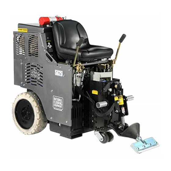
Features and Specifi cations Control Levers Cutting Head Non-marking Tires Cylinder Lift Adjustable Foot Pegs Adjustable Slide Plate Quick-change Swivel Head Fork Lift Cups Debris Defl ector FEATURES Non-marking Tires - Large non-marking tires, work on Control Levers - Forward, reverse, turn and break with all types of application and debris build-up. -
Page 6: Safety
Safety GENERAL RULES FOR SAFE OPERATION READ AND SAVE ALL INSTRUCTIONS FOR FUTURE USE. Before use, be sure everyone operating this equipment reads and understands this manual as well as any labels packaged with or attached to the machine and components and view the instructional video. Extra copies of the manual and video are available. -
Page 7: Characteristics Of A Defensive Operator
Safety CHARACTERISTICS OF A DEFENSIVE OPERATOR A GOOD OPERATOR IS A “DEFENSIVE” OPERATOR! Qualities Include: Education: Educates themself about the machine and the environment. Alert: Stays alert. Do not let guard down. Skills: Only performs duties he/she are qualifi ed to do. Always tries to improve. Judgment: Plays it safe. -
Page 8: Safety Switch
USE CARBON MONOXIDE DETECTOR WHEN OPERATING MACHINE Included with the 5625 are a 75007 lapel CO Monitor and a 75008 Clip. it is recommended that the operator and anyone in the working vicinity wear the detector. Failure to do so could cause bodily injury and/or death. The use of detectors helps to verify if work area is safe from Carbon Monoxide poisoning. - Page 9 GASES, DUST, STEAM, SMOKE Do not weld, fl ame cut or perform grinding work on the 5625 Propane Ride-On without written authorization from the manufacturer. The danger of fi re or explosion exists when work of this nature is done. Begin maintenance work only when the machine is in Shut Down Mode (turned off).
-
Page 10: Machine Operation
Machine Operation LOADING/UNLOADING Caution Do Not “Side Hill” • Always remove blade and cutting head when machine is being moved or trans- ported • Cutting head and slide plate can be removed to make the machine more compact. • NEVER leave machine unattended on an incline. •... -
Page 11: Job Site Movement
Machine Operation WHEEL CHOCKS Wheel chocks will help to secure the machine but DO NOT use wheel chocks alone to secure the machine. CENTER OF GRAVITY Be aware of your surroundings and machines operating angles. When changing from a low slide plate to a high slide plate setting or a low cutting head angle to a high cutting head angle, the operating “attitude”... -
Page 12: Wheel Size
Machine Operation TO MOVE MACHINE WITHOUT POWER (PUSHING MACHINE) Forward: To move the machine forward, levers need to be pushed forward. To lock levers in place, connect a bungee-strap from each lever (pushing levers forward), pulling straps down to and connecting to the front plate (See Figure K). Never leave machine unattended with strap holding levers open. -
Page 13: Start Up Procedure
Machine Operation START UP PROCEDURE Key Start POWER /Key Start (Figure M) Open propane tank valve by turning knob counterclockwise until fully open. The machine will not start unless the operator is properly seated. Insure that hydraulic levers are “centered”. Set throttle at a quarter open. -
Page 14: Seat Switch
IN USE. SHUT DOWN MODE (SHUT DOWN PROCEDURE/ TURNED OFF) Defi nition: State or condition of the 5625 Propane Ride-On that minimizes the danger of mechanical, electrical, pneumatic or hydraulic hazards. Putting the 5625 Propane Ride-On in Shut Down Mode: •... -
Page 15: Changing The Propane Tank
Follow steps in reverse order. CARBON MONOXIDE DETECTOR (FIGURE Z) Included with the 5625 are a 75007 Lapel CO Monitor and a 75008 Clip. It is recom- mended that the operator and anyone in the working vicinity wear the detector. Failure to do so could cause bodily injury and/or death. -
Page 16: Cutting Head & Blades
Machine Operation CUTTING HEAD & BLADES DIALING IN THE MACHINE Dialing in the machine is matching the correct cutting head, blade size, blade angle and added weight to the machine to make the material removal as easy as possible. For every material being removed, there is an optimum blade width, thickness, sharpness, angle and bevel (bevel up or bevel down). -
Page 17: Blade Setting
Machine Operation STEEP CUTTING HEAD ANGLE A steep angle is only used for re-scraping. The slide plate has to be raised so the bottom of the slide plate is higher or even with the bottom of the guide channels (See Figure DD). - Page 18 Machine Operation BLADE INSERTION OR BLADE CHANGING Blade Securing Bolt Cutting Head Using a 3/4’’ socket wrench, loosen bolts on cutting head. Quantity of bolts will very de- pending upon cutting head size. Insert blade into the cutting head to back of notch (See Figure FF).
- Page 19 Machine Operation VCT TILE SET-UP The slide plate should be adjusted to a low setting (1”) one inch off the fl oor. If goods come up easily, change to a larger Cutting Head. If goods come up harder, use a Cutting Head from 6” to 8” with a Premium High Tempered Blade (.062) to match cutting head size. Sometimes a .094 blade may work better.
-
Page 20: Ditching
Machine Operation DITCHING CROSS ROOM DITCHING When removing hard to remove ceramic, Vct or vat, cross-room ditching will help to make the removal easier. Using a blade 2” to 6” in width, make ditches 1’ to 2’ apart in the same direction the machine will be removing the goods (See Figure HH). This “relieves” the pressure holding the tiles together. -
Page 21: Blades
Blades STANDARD BLADE (FIGURE LL) This heavy duty blade is designed to remove soft goods, carpet, and vinyl fl ooring. Its .062 thickness offers fl exibility to maximize the shear point angle. PART# DESCRIPTION THICKNESS (IN.) 5” X 16” BLADE .062 5”... - Page 22 Blades EXTRA HEAVY DUTY BLADES (FIGURE PP) These extremely hard, high abrasion alloy blades are designed for tough tear up situations. VCT, VAT, wood, tile, lighter ceramic, re-scraping thin-set, all carpets, cork, elastomeric coatings, re-scraping rubber and urethane coatings. They hold all edges extremely well. PART# DESCRIPTION THICKNESS (IN.)
- Page 23 Blades TAPERED CUTTING HEAD SHANKS (FIGURE UU) The longer taper works great on tough wood fl oors (glued & nailed). The long length allows the blade to easily slide under tough materials. They work through most ceramics and VCT. PART# DESCRIPTION THICKNESS (IN.) 7075-8...
-
Page 24: Machine Maintenance
Machine Maintenance SLIDE PLATE Slide Plate TO REMOVE SLIDE PLATE Disconnect machine from power. Loosen Slide Remove slide plate pin. Remove cutting head bolt. Remove cylinder from slide Plate plate. Remove slide plate. Bolts Disconnect Loosen Disconnect machine from power. Screw Unplug hydraulic lines from cylinder. -
Page 25: Hydraulic Oil Change Out
Machine Maintenance HYDRAULIC OIL CHANGE OUT Let Hydraulic fl uid cool before maintenance. Check Oil Here Disconnect machine from battery. Add Oil Here Drain fl uid by removing the drain plug from side of tank (See Figure ZZ). Take Caution: this unit contains twelve gallons of fl uid. Make sure you have the proper amount of containers to catch fl... -
Page 26: Pump Change Out
Machine Maintenance PUMP CHANGE OUT Lift and secure hood. Disconnect hydraulic lines. Remove two 3/8”-16x1 pump bolts. Remove pump by pulling pump straight out from pump motor. VALVE CHANGE OUT Disconnect machine from power (charger or battery). FIG. AC Lift hood and secure in place. Remove hoses from valve body. -
Page 27: Changing Hydraulic Fluid Filter
Machine Maintenance CHANGING FILTER (FILTER SHOULD BE REPLACED YEARLY) Place pan or rag below fi lter to catch excess hydraulic fl uid. Unscrew fi lter by hand or with wrench. Use excess hydraulic fl uid to lubricate seal on new fi lter. Hand tighten replacement fi... -
Page 28: Debris Defl Ector Mounting Instructions
Machine Maintenance DEBRIS DEFLECTOR (#5200-258) MOUNTING INSTRUCTIONS Insert & Secure Insert and secure a cutting head, making sure cutting head is all the way in. Debris Defl ector Cutting Head If there are holes on your lower cutting head support, place debris defl ector under the lower cutting head support and bolt in place. -
Page 29: Troubleshooting Guide
Troubleshooting Guide Problem Cause Solution 1. Scraper does not work when pump is a. Severe blockage in wheel drive motor a. Check hoses for blockage and replace generating pressure. hoses hose if necessary b. Wheel drive motors defective b. Call National service center 2. - Page 30 Troubleshooting Guide (Cont.) Problem Cause Solution 11. Red ignition light stays on. a. Oil is Low. a. Fill engine oil to proper level. b. Machine is overheating. b. Let engine cool. Add coolant to proper level. 12. Machine doesn’t start. a.
-
Page 31: Complete Parts List
3/8 “ 90° PUMP FITTING 61 402003 NATIONAL LABEL, SMALL 9 73008 1/4-20 NYLON LOCK NUT 62 402012 5625 STOCK NUMBER LABEL 10 73020 1/4-20 X 5/8 WIZLOCK BOLT 63 400191-1 EXAUST, MUFFLER 11 73021 1/4-20 X 2¼ HEXHEAD CAP SCREW... - Page 32 Complete Parts List PART# DESCRIPTION PART# DESCRIPTION 107 5600-57 SAFETY SHUT OFF BRACKET 125 L08-1 STAND CLEAR LABEL 108 5600-58 VALVE LEVER - SHORT 126 L106 PINCH POINT LABEL 109 5700-36 HOSE GUARD 127 L118 OPERATOR MUST BE SEATED LABEL 110 5700-54 HANDLE GRIP SLEEVE 128 L137...
-
Page 33: Parts List And Diagrams
Parts List and Diagrams EXTERNAL PARTS PART# DESCRIPTION PART# DESCRIPTION 1 5110-111 SEAT 8 5600-300 18” WHEEL RIM & TIRE 2 5600-21 HANDLE WELDMENT, LEFT 9 70602 INSTRUCTION MANUAL TUBE 3 5600-22 HANDLE WELDMENT, RIGHT 10 5110-180 PEG, FOOT 4 401563-SV HOOD, RIDE-ON, SILVER VEIN 11 5110-207 SWITCH, SEAT... -
Page 34: External Parts
Parts List and Diagrams EXTERNAL PARTS PART# DESCRIPTION PART# DESCRIPTION 1 401567 SLIDE PLATE CAST 5 5200-194 DOUBLE WHEEL CASTER ASSEMBLY (GRAY) 1 2 401568 LOWER CUTTING HEAD SUPPORT 6 5700-36 HOSE GUARD 3 5110-180 FOOT PEG 7 401429 PIN, LOWER CUTTING HEAD SUPPORT 4 5110-250 CYLINDER Fax: 763-535-8255... -
Page 35: Backup Beeper Assembly
Parts List and Diagrams PART# DESCRIPTION BACKUP BEEPER ASSEMBLY 1 5200-116 BACK-UP BEEPER ASSEMBLY PART# DESCRIPTION HANDLE SWITCH (FOR BEEPER) 1 5110-218 BACK-UP BEEPER SWITCH 2 74513 6-32 X 3/4 PHILLIPS PANHEAD MACHINE SCREW PART# DESCRIPTION INSTRUCTION TUBE PARTS 1 70602 INSTRUCTION MANUAL TUBE 2 70603 INSTRUCTION TUBE CAP... -
Page 36: Gear Pump Parts
Parts List and Diagrams GEAR PUMP PARTS PART# DESCRIPTION PART# DESCRIPTION 1 5200-1G DOUBLE PUMP GASKET 5 73203 3/8 SAE FLAT WASHER 2 70905-D7 DOUBLE GEAR PUMP 6 73204 3/8 SPLIT LOCK WASHER 3 72816 3/8 “ 90° PUMP FITTING 7 6280-118 FITTINGS 4 73201... -
Page 37: Wheel Parts
Parts List and Diagrams WHEEL PARTS PART# DESCRIPTION PART# DESCRIPTION 1 400133 HIGH SPEED HYD. WHEEL MOTOR 5 73047 1/4 X 1 WOODRUFF KEY 2 5110-114-2 WHEEL MOTOR FITTING 6 73131 3/32 X 1¾ KOTTER PIN 3 5110-117 WHEEL HUB 7 73430 1/2-20 NYLON LOCK NUT 4 5110-117-2... -
Page 38: Control Lever Parts
Control Lever Parts CONTROL LEVER PARTS PART# DESCRIPTION PART# DESCRIPTION 1 5110-271 LEVER BRACKET 11 400327 HANDLE RUBBER COVER 2 5110-272 CYLINDER LIFT LEVER ONLY 12 73020 1/4-20 X 5/8 WIZLOCK BOLT 3 5200QL-11-LH-W SINGLE SPOOL VALVE 13 73202 3/8 INTERNAL LOCK WASHER 4 5200QL-11-RH-W DOUBLE SPOOL VALVE 14 73213 3/8-16 X 3/4 BUTTON HEAD CAP SCREW 3... -
Page 39: Single Spool & Hose Parts
Parts List and Diagrams SINGLE SPOOL & HOSE PARTS PART# DESCRIPTION PART# DESCRIPTION 1 5110-115 SINGLE SPOOL CONTROL 6 73021 1/4-20 X 2¼ HEXHEAD CAP SCREW 2 5200-261 WHEEL MOTOR LINE 7 73308 5/16-18 X 3/4 BUTTON HEAD CAP SCREW 3 5700-77 SUCTION LINE 4 70651... -
Page 40: Double Spool & Hose Parts
Parts List and Diagrams DOUBLE SPOOL & HOSE PARTS PART# DESCRIPTION PART# DESCRIPTION 1 5110-116 DOUBLE SPOOL CONTROL 6 73021 1/4-20 X 2¼ HEXHEAD CAP SCREW 2 5110-267 CYLINDER LINE HOSES W/ SHEATH 7 73324 5/16-18 X 3¼ SOCKET HEAD CAP SCREW 1 3 5110-268 STRAIGHT VALVE FITTING 8 70651... -
Page 41: Filter & Tank Parts
Parts List and Diagrams FILTER & TANK PARTS PART# DESCRIPTION PART# DESCRIPTION 1 5110-237 SUCTION FILTER SCREEN 7 5700-70 T-FITTING (INSIDE HYDRAULIC TANK) 8 5700-71 HOSE (RETURN, RIGHT) 2 5200-604 FILTER BLOCK 9 5700-75 HOSE (PRESSURE, LEFT-12.5) 3 5700-64 FILTER FITTING 10 5700-76 HOSE (PRESSURE, RIGHT-25) 4 5700-65... -
Page 42: Cylinder Parts
Parts List and Diagrams CYLINDER PARTS PART# DESCRIPTION 1 5110-250 CYLINDER 2 5110-251 CYLINDER CONNECTING ROD 3 73536 CYLINDER CLIP 4 72801 1/4″ 90° FITTING 5 73402 1/2-13 NYLON LOCK NUT 6 73410 1/2-13 X 3½ HEXHEAD BOLT PART# DESCRIPTION 1 5700-36 HOSE GUARD 2 73322... -
Page 43: Slide Plate
Parts List and Diagrams PART# DESCRIPTION SLIDE PLATE/DEFLECTOR PARTS 1 401429 PIN, CUTTING HEAD 2 400132 BOLT, HEX HEAD, 1/2-13 X 4, GRADE 8 3 73402 NUT, NYLOCK 1/2-13 4 401568 SUPPORT, TOOLING CARRIER, CAST 5 73408 3/4-10 X 1 1/2 HEXHEAD BOLT G8 ZINC 6 401567 SLIDE PLATE, DUAL LIFT, CAST PART#... -
Page 44: Propane Tank Parts
Parts List and Diagrams PROPANE TANK PARTS PART# DESCRIPTION 1 5600-25 PROPANE TANK HOLD DOWN BRACKET 1 2 5600-56 PROPANE HOLD DOWN BOLT 3 7050-P PROPANE TANK (1 IN MACHINE & 1 SPARE) 2 4 73201 3/8-16 X 1 HEXHEAD CAP SCREW CARBON MONOXIDE MONITOR PART# DESCRIPTION... -
Page 45: Engine Parts
Parts List and Diagrams ENGINE PART# DESCRIPTION PART# DESCRIPTION 1 5200QL-27 MAIN BASE (NOT SHOWN) 10 70953 SPIDER (NOT SHOWN) 2 5600-34 ENGINE BASE WELDMENT 11 70954 LOVEJOY COUPLER LO 95 X 1¼ 3 5600-53 REGULATOR BRACKET 12 74701 3/4” ID GROMMET 4 5600-57 SAFETY SHUT OFF BRACKET 13 74702... -
Page 46: Battery
Parts List and Diagrams BATTERY PART# DESCRIPTION 1 5600-13 BATTERY HOLD DOWN 2 5600-121 BATTERY, 12 VOLT, 55 AGM 3 73342 5/16-18 X 5 HEXHEAD CAP SCREW PART# DESCRIPTION WEIGHTS 1 5110-404 REAR WEIGHT 2 74854 FRONT WEIGHT INDIVIDUALLY-36 LB. 3 73403 1/2 SPLIT LOCK WASHER 4 73406... -
Page 47: Labels
NATIONAL LABEL, LARGE 21 L319 BURN HAZARD LABEL 9 L223 PATENT NUMBER LABEL 22 L01 CAUTION 3 X 1/2 10 402012 5625 STOCK NUMBER LABEL 11 L314 LP GAS LABEL 12 L315 CARBON MONOXIDE LABEL 13 L08-1 STAND CLEAR LABEL www.nationalequipment.com... -
Page 48: Accessories
Accessories TILE BOX The Tile Box works for wind rowing and assists for a fast clean-up and collection of tile debris for quick removal. High abrasion alloy for a long lasting edge. Resharpens just like a blade. 5” x 27” x 6” box. Attaches to the #7050-27 Cutting Head (required). - Page 49 Accessories PROPANE TANK Vapor tank can hold approximately 14.25 pounds of propane. Includes gauge and fi ll valve. Designed to withstand high impact. 7050-P Propane Tank LAPEL CARBON MONOXIDE CLIP Carbon Monoxide detector badge, convenient to have on the jobsite when CO gas could be present •...
-
Page 50: Wiring Diagram
Parts List and Diagrams 5625 WIRING DIAGRAM Fax: 763-535-8255 info@nationalequipment.com... -
Page 51: Material Safety Data Sheet
Material Safety Data Sheet (MSDS) Information CHEVRON HD 22 - 68 - HYDRAULIC FLUID PRODUCT IDENTIFICATION AND COMPANY IDENTIFICATION Product Number(S): CPS221655, CPS221658, CPS221659 CHEMTREC: (800) 424-9300 or (703) 527-3887 Synonyms: Texaco Rando HD22, Texaco Rando HD 32, Texaco Health Emergency Rando HD 46, Texaco Rando HD 68 Chevron Emergency Information Center: Located in the USA. - Page 52 Material Safety Data Sheet (MSDS) Information CHEVRON HD 22 - 68 - HYDRAULIC FLUID (CONTINUED) EXTINGUSHING MEDIA: Use water fog, foam, dry chemical or carbon dioxide (CO2) to extinguish fl ames. PROTECTION OF FIRE FIGHTERS: Fire Fighting instructions: This material will burn although it is not easily ignited. For fi res involving this material, do not enter any enclosed or confi...
- Page 53 Chevron HD 22 - 68 - hydraulic fl uid (continued) REGULATORY INFORMATION EPCRA 311/312 CATAGORIES: 1. Immediate (Acute) Health Effects: NO 2. Delayed (Chronic) Health Effects: NO 3. Fire Hazard: NO 4. Sudden Release of Pressure Hazard: NO 5. Reactivity Hazzard: NO REGULATORY LISTS SEARCHED: 01-1=IARC Group1 03=EPCRA 313...
- Page 54 Chevron HD 22 - 68 - hydraulic fl uid (continued) CHEVRON HD 22 - 68 - HYDRAULIC FLUID (CONTINUED) PHYSICAL AND CHEMICAL PROPERTIES Attention: The data below are typical values and do not constitute a specifi cation. Color: Yellow Physical State: Liquid Odor: Petroleum odor pH: Not applicable Vapor Pressure: <0.01 mmHg @ 37.8 C (100 F)
- Page 55 Fire Extinguisher - MSDS www.nationalequipment.com Phone: 763-315-5300...
- Page 56 Fire Extinguisher - MSDS (Continued) Fax: 763-535-8255 info@nationalequipment.com...
- Page 57 Fire Extinguisher - MSDS (Continued) www.nationalequipment.com Phone: 763-315-5300...
- Page 58 Fire Extinguisher - MSDS (Continued) Fax: 763-535-8255 info@nationalequipment.com...
- Page 59 Fire Extinguisher - MSDS (Continued) www.nationalequipment.com Phone: 763-315-5300...
- Page 60 Fire Extinguisher - MSDS (Continued) Fax: 763-535-8255 info@nationalequipment.com...
- Page 61 Fire Extinguisher - MSDS (Continued) www.nationalequipment.com Phone: 763-315-5300...
-
Page 63: Guarantee
This warranty gives you specifi c legal rights. You may also have other rights which vary from state to state. WARRANTY PERIOD The 5625 Propane Powered Floor Prep System is guaranteed to be free of manufacturer defective workmanship and in quality of materials for a period of one year. - Page 64 9250 Xylon Avenue N • Minneapolis, MN 55445 • U.S.A. Toll-free 800-245-0267 • Phone 763-315-5300 • Fax 800-648-7124 • Fax 763-535-8255 Web Site: www.nationalequipment.com • E-Mail: info@nationalequipment.com...
Need help?
Do you have a question about the 5625 and is the answer not in the manual?
Questions and answers