
Related Manuals for National Flooring Equipment 5700-aus


Summary of Contents for National Flooring Equipment 5700-aus
-
Page 1: Instruction Manual
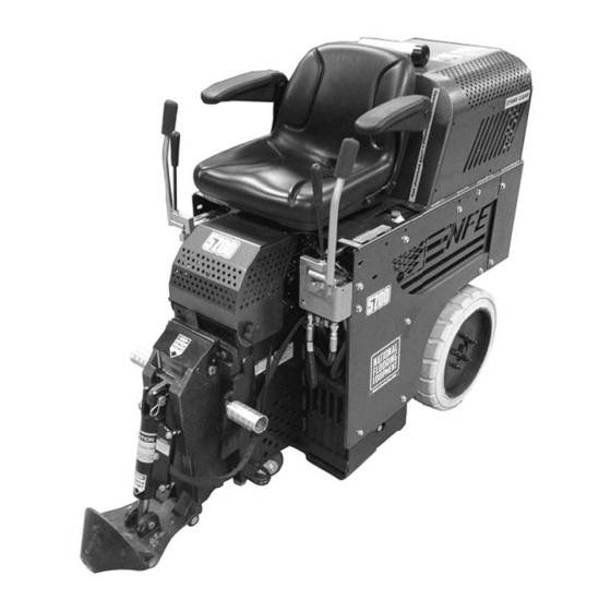
Rev B ALL DAY BATTERY RIDE-ON SCRAPER INSTRUCTION MANUAL Read Manual Before Operating Machine 401810... -
Page 3: Table Of Contents
Table of Contents Table of Contents ............................... 3-4 Features and Specifi cations ............................5 Safety ................................... 6-8 General Rules For Safe Operation ........................6-7 Characteristics of a Defensive Operator ........................ 7 Hydraulic Safety Tips ............................. 7 Silica Dust Warning ..............................8 Battery/Charger Information ............................ -
Page 4: Table Of Contents
Table of Contents Gear Pump Assembly ............................40 Labels .................................. 41 Weights & Wrench ............................... 42 Battery Wiring ..............................43 Seat Wiring ................................44 Machine Wiring ..............................45 Accessories ..............................46-47 Material Safety Data Sheet (MSDS) Information ....................48-55 Guarantee ..................................57 Fax: 763-535-8255 info@nationalequipment.com... -
Page 5: Features And Specifi Cations
Features and Specifi cations Control Levers Kill Switch within the seat DC Motor Pump Compartment On Board Battery Charger 18” Wheels Adjustable Foot Rests Adjustable Slide Plate Cutting Head Cylinder Lift Fork Lift Cups Debris Defl ector Removable Swivel Cutting Head FEATURES Kill Switch - Insures the machine will not function without someone in DC Motor Pump Compartment - Easy access for maintaining the... -
Page 6: Safety
All operators must view the instruction video. Extra copies of the manual and video are avail- able by contacting National Flooring Equipment. KNOW YOUR EQUIPMENT: Read this manual carefully to learn equipment applications and limitations, potential hazards associated with this type of equipment. -
Page 7: Characteristics Of A Defensive Operator
Safety 25. STORE IDLE EQUIPMENT: When not in use, store in a dry, secured place. Keep away from children. 26. MAINTAIN LABELS AND NAMEPLATES: These carry important information. If unreadable or missing, contact National for a replace- ment. 27. MACHINE IS HEAVY, DO NOT DROP. Ensure proper lifting procedures are followed when transporting. 28. -
Page 8: Silica Dust Warning
SAFETY SWITCH The 5700-AUS All Day Battery Powered Ride-On has been equipped with a safety switch under the seat, which requires the operator to be seated before the 5700-AUS can be operated. Do not attempt the start-up procedure with out being seated on the machine. -
Page 9: Battery/Charger Information
Battery/Charger Information CHARGER INSTRUCTIONS Check that the temporary label on top of the charger marked with the profi le setting matches your battery type. These chargers work very simply. Once connected and plugged into AC power, the LED will fl ash red for a few seconds, then turn steady red. When the cycle is 80% complete it will turn yellow, and fi... -
Page 10: Machine Charging
Battery/Charger Information MACHINE CHARGING Machine has an on board charger (Figure B). To eliminate accidental machine start-up while charging depress E-Stop Button (Figure C) before connecting to power source. Connect to power source using a 3 meter (10 foot) extension cord. NOTE: Not us- ing the proper gauge &... -
Page 11: Commonly Asked Questions
Battery/Charger Information COMMONLY ASKED QUESTIONS Question: When the charging battery has not been fully discharged will it take a memory set? Answer: No, the design of these batteries allow charging at any stage of discharge without memory problems. Question: Do I lose a complete cycle when I charge batteries that are only partially discharged? Answer: No when 70% or higher useable charge is left. -
Page 12: Battery Troubleshooting
Battery/Charger Information Problem Cause Solution When plugged into AC power LED fl ashes Connected reverse to battery, or not con- Correct polarity, or connect to battery. red/green. nected to battery. Break in DC cord, or connector. Have a qualifi ed person make repair. Battery too dead to charge. -
Page 13: Machine Operation
Machine Operation LOADING/UNLOADING SAFETY PRECAUTIONS • Always remove blade and cutting head when machine is being moved or trans- ported. • Cutting head and slide plate can be removed to make the machine more compact. • NEVER leave machine unattended on an incline. •... -
Page 14: Center Of Gravity
Machine Operation TRANSPORTING Secure machine with ratchet straps when transporting the machine. Chock wheels to keep machine from rolling, hydraulic levers should not be locked in the forward or backward position. Hydraulic levers should be straight up in the “neutral” position. This helps to lock drive wheels. -
Page 15: Operating Controls
Machine Operation OPERATING CONTROLS POWER ON SWITCH (FIGURE O) Never use the power ON switch as a method for speed control. Speed control is achieved by the hydraulic valve only. Using the on/off switch repeatedly will cause exces- sive wear, causing premature replacement of electrical components. An Emergency Stop Switch (E-Stop) is located by right hand (Figure P). -
Page 16: Operational Tips
Machine Operation CYLINDER LIFT (FIGURE T) The cylinder lift lever raises and lowers the cylinder and cutting head. After setting slide plate to proper height, use the cylinder lift lever to set blade to proper cutting angle. Pull back on the cylinder lift lever to raise the cutting head. -
Page 17: Dialing In The Machine
Machine Operation DIALING IN THE MACHINE Dialing in the machine is matching the correct cutting head, blade size, blade angle and blade width to the machine to make the material removal as easy as possible. For every material being removed, there is an optimum blade width, thickness, sharpness, angle and bevel (bevel up or bevel down). - Page 18 Machine Operation SHEAR POINT The shear point is the point where material to be removed will cut cleanly from the fl oor. If the blade is too wide, too dull, or too steep, the shear point is lost. WEIGHT VS. SHARPNESS The most common way to compensate for a dull blade is to add more weight and raise the blade angle (see high setting).
-
Page 19: Applications Set-Up
Machine Operation SHANK BLADE INSERTION Shank blades (Figure AA) do not require a cutting head. Insert desired shank blade into cutting head holder. Secure with cutting head clip. BLADE INSERTION OR BLADE CHANGING (FIGURE BB) Using a 3/4’’ socket wrench, loosen bolts on cutting head. Quantity of bolts will very depending upon cutting head size. - Page 20 Machine Operation WOOD SET-UP (FIGURE DD) The slide plate should be adjusted to a low setting 2.5 cm (1”) off the fl oor. Use Shank Blades, Shank Blades with carbide tips or a 15 to 18 cm (6”or 8”) Cutting Head with Shoe Blades, Bent Shoe Blades or Heavy Duty Blades.
-
Page 21: Ditching
Machine Operation WORKING OVER WOOD A heavy machine cannot be used on wood subfl oors or raised panel computer fl oors. Keep machine light, remove all weights. A weighted machine could break through the fl oor. The slide plate should be adjusted to a low setting 2.5 cm (1”) off the fl oor. Blades should be as fl... -
Page 22: Blades
Blades CUTTING HEADS (FIGURE JJ) Swivel heads rotate to use the second sharp edge of the blade without having to remove the blade. Swivel head allows blade to stay in contact with the fl oor. PART# DESCRIPTION 7050-6 6’’ CUTTING HEAD 7050-8 8’’... - Page 23 Blades EXTRA HEAVY DUTY BLADES (FIGURE NN) Extremely hard, high abrasion alloy for tough tear up situations. VCT, VAT, wood, tile, lighter ceramic, rescraping thin-set, all carpets, cork, elastomeric coatings, rescraping rubber and urethane coatings. Holds the edge extremely well. PART# DESCRIPTION THICKNESS (IN.)
- Page 24 Blades TAPERED CUTTING HEAD SHANK BLADES (FIGURE SS) The longer taper works great on tough wood fl oors (glued & nailed). The long length allows the blade to easily slide under tough material. Works well on most ceramics and VCT. PART# DESCRIPTION THICKNESS (IN.)
-
Page 25: Blade Sharpening
Blades 1” BLADES (FIGURE XX) Short profi le blades where a rigid blade application is needed. Thickness greatly reduces breakage. Used for VCT & adhesive rescrape. Works well for parking deck coatings, epoxies & elastomeric coatings. PART# DESCRIPTION THICKNESS (IN.) 7091 1”... -
Page 26: Machine Maintenance
Machine Maintenance CAUTION: ALWAYS DISCONNECT BATTERY BEFORE MAINTAINING. LOWER CUTTING HEAD SUPPORT REMOVAL Lower slide plate so cutting head hinge pin is below machine bottom. Retighten. Loosen both cutting head pin set screws (G) at the base of the lower cutting head support (hinge area). -
Page 27: Checking Oil Level
Machine Maintenance LEAK MAINTENANCE All fi ttings on this machine are O-ring style. Disconnect machine from power. If a leak is detected, tighten fi tting with the proper wrench size. DO NOT over tighten. Over tightening could damage O-rings. CHECK OIL LEVEL Remove Breather Dip Stick (G). -
Page 28: Pump Change Out
Machine Maintenance PUMP CHANGE OUT Remove doghouse to expose pump. Disconnect hydraulic lines. Remove two 5/16” pump securing bolts. Remove pump by pulling pump straight out from pump motor. VALVE CHANGE OUT Disconnect machine from power (charger or battery). Lift hood and secure in place. FIG. -
Page 29: Seat Replacement
Machine Maintenance CASTER WHEEL MAINTENANCE Keep clean and free of debris, make sure it can move freely. Give a shot of grease in grease fi tting on caster every six months to keep moving freely. To remove caster, machine will need to be raised. Push the cylinder lift lever for- ward to lower and adjust the angle of the cutting head to jack up the machine (Figure AG). -
Page 30: Troubleshooting Guide
Troubleshooting Guide Problem Cause Solution Machine will not start. Seat Safety Switch is engaged. Make sure that you’re sitting on seat. Emergency Stop (E-Stop) switch is engaged. Twist E-Stop switch to expose green ring. Circuit breaker is in the OFF position. Verify circuit breaker is in ON position. -
Page 31: Complete Parts List
Complete Parts List PART# DESCRIPTION PART# DESCRIPTION 1 70354 HOSE, 3/4”, RETURN LINE TO TANK 55 401553 BATTERY CHARGER, INBOARD 2 70355 HOSE, 3/4”, RETURN LINE TO FILTER 56 401567 SLIDE PLATE, DUAL LIFT, CAST 3 70602 TUBE, INSTRUCTION MANUAL 57 401568 SUPPORT, TOOLING CARRIER, CAST 4 70603... - Page 32 FITTING, SUCTION HOSE TO PUMP 143 L95F LABEL, FLUID LEAK 125 70905-D4 PUMP, DOUBLE, MARZOCCHI 144 L98 LABEL, BLADE LIFT 126 L08-1 LABEL, STAND CLEAR 145 401810 MANUAL, 5700-AUS 127 L106 LABEL, PINCH POINT 146 6701-10 ASSEMBLY, VALVE BRACKET www.nationalequipment.com Phone: 763-315-5300...
-
Page 33: Parts List And Diagrams
Parts List and Diagrams EXTERNAL PARTS PART# DESCRIPTION PART# DESCRIPTION 1 5110-111 SEAT, RIDE ON 11 401570 TRAY, BATTERY, UPPER 2 5110-180 PEG, FOOT 12 5600-21 HANDLE, WELDMENT RIGHT 3 5110-250 CYLINDER NN16 13 5600-22 HANDLE, WELDMENT LEFT 4 5110-251 ROD, CYLINDER CONNECT 14 73212 BOLT, BUTTON HEAD CAP 3/8 16X1/2... -
Page 34: Cylinder Assembly
Parts List and Diagrams CYLINDER ASSEMBLY PART# DESCRIPTION 1 5110-250 CYLINDER NN16 2 5110-251 ROD, CYLINDER CONNECT 3 72801 FITTING, 90 DEGREE, 1/4” 4 400132 BOLT, HEX HEAD, 1/2 13 X 3 1/2 5 73402 NUT, NYLOCK 1/2 13 6 73536 PIN, HITCH CLIP 5/8”... -
Page 35: Caster Wheel Assembly
Parts List and Diagrams PART# DESCRIPTION CASTER WHEEL ASSEMBLY 1 5200-194 CASTER, DOUBLE GRAY 2 73427 BOLT, HEX HEAD CAP 1/2 13X1 1/2 3 73424 WASHER, FLAT, ZINC SAE 1/2 4 73403 WASHER, SPLIT LOCK 1/2 PART# DESCRIPTION REAR WHEEL ASSEMBLY 1 400133 MOTOR, WHEEL, HYDRAULIC, 10MM BOLT 2 2 5110-114-2... -
Page 36: Electrical Box Assembly
Parts List and Diagrams ELECTRICAL BOX ASSEMBLY PART# DESCRIPTION 1 5200-118-8 CONNECTOR, BLUE 48V BATTERY 2 5200-127 STRIP, ELECTRICAL 3 5700-100 WIRE SET (PARTIAL SHOWN) 4 5700-104 CONTACTOR 5 5700-106 BREAKER, CIRCUIT, 70 AMP 6 72705 PLUG, 48V 7 5700-85 COVER, TERMINAL STRIP 8 5700-80 HARNESS, MAIN... -
Page 37: Backup Beeper Assembly
Parts List and Diagrams PART# DESCRIPTION BACKUP BEEPER ASSEMBLY 1 5200-116 BEEPER, BACK UP PART# DESCRIPTION HANDLE SWITCH (FOR BEEPER) 1 5110-218 SWITCH, BACK UP BEEPER 2 74517 SCREW, PHILLIPS PAN HEAD MAC 6 32X1 2 PART# DESCRIPTION INSTRUCTION TUBE ASSEMBLY 1 70602 TUBE, INSTRUCTION MANUAL 2 70603... -
Page 38: Spool And Hose Parts
Parts List and Diagrams SPOOL AND HOSE PARTS PART# DESCRIPTION 1 400133 MOTOR, WHEEL, HYDRAULIC, 10MM BOLT 2 2 5110-114-2 FITTING, WHEEL MOTOR 3 5110-116 SPOOL CONTROL, DOUBLE 4 70651 PLUG, VALVE BODY 5 72816 FITTING, ELBOW, 90 DEGREE, 3/8” 6 5110-268 FITTING, VALVE STRAIGHT 7 5200-1G... -
Page 39: Hydraulic Flow Diagram
Parts List and Diagrams HYDRAULIC FLOW DIAGRAM 13 14 THE ASSOCIATED NUMBERS FOR THESE CALLOUTS ARE ON PAGE 38 Fax: 763-535-8255 info@nationalequipment.com... -
Page 40: Motor
Parts List and Diagrams MOTOR PARTS PART# DESCRIPTION 1 72385 MOTOR, 4 HP, XP2135 2 5200QL-1A PLATE, HYDRAULIC PUMP ADAPTOR 3 73242 SCREW, BH CAP WITH FLANGE 3/8 16 X 1 4 4 5200-18 CLAMP, FRONT MOTOR 5 73201 SCREW, HEX HEAD CAP 3/8 16X1 6 73204 WASHER, SPLIT LOCK 3/8 7 5700-35... - Page 41 Parts List and Diagrams Parts List and Diagrams CONTROL LEVER PARTS PART# DESCRIPTION PART# DESCRIPTION 1 401403 LEVER BRACKET 11 73020 1/4-20X5/8 WIZLOCK BOLT 2 5700-60 CYLINDER LEVER LIFT ONLY 12 73202 3/8 INTERNAL LOCK WASHER 3 5200QL-13 VALVE LEVER SPACER 13 73213 3/8-16X3/4 BUTTON HEAD CAP SCREW 4 5600-21...
-
Page 42: Labels
Parts List and Diagrams Parts List and Diagrams LABELS PART# DESCRIPTION PART# DESCRIPTION 1 L08-1 LABEL, STAND CLEAR 12 L33B LABEL, CAUTION MOVING PART 2 L106 LABEL, PINCH POINT 13 L33C LABEL, INSTRUCTION MANUAL 3 L118 LABEL, OPERATOR MUST BE SEATED 14 L33D LABEL, AUTHORIZED PERSONEL ONLY 4 L127... - Page 43 Parts List and Diagrams PART# DESCRIPTION WEIGHTS 1 74854 WEIGHT, 36 LB. REMOVABLE 2 73424 WASHER, FLAT, ZINC SAE 1/2 3 73403 WASHER, SPLIT LOCK 1/2 4 73414 BOLT, HEX HEAD 1/2 13X7 5 73406 SCREW, CAP HEXHEAD 1/2-13 X 1-1/4 PART# DESCRIPTION BATTERY FUEL GAUGE...
-
Page 44: Battery Wiring
Parts List and Diagrams 5700 BATTERY WIRING Fax: 763-535-8255 info@nationalequipment.com... -
Page 45: Seat Wiring
Parts List and Diagrams 5700 SEAT WIRING WHITE BLACK E-STOP BATTERY METER BLUE BLACK BLUE Brown START HOUR METER Brown SEAT SWITCH www.nationalequipment.com Phone: 763-315-5300... -
Page 46: Machine Wiring
Parts List and Diagrams 5700 MACHINE WIRING Fax: 763-535-8255 info@nationalequipment.com... - Page 47 Parts List and Diagrams TILE BOX Part 7074 The Tile Box works for wind rowing and assists for a fast clean-up and collection of tile debris for quick removal. High abrasion alloy for a long lasting edge. Resharpens just like a blade.
- Page 48 Parts List and Diagrams HYDRAULIC SLIDE PLATE Part 6701 Cutting head slide plate assembly is now available with hy- draulic operation. Provides the operator the ability to adjust the height of the slide plate and allows precise angle adjust- ment of the cutting head with hydraulic hand control. No need to get off the machine, no lifting and no manual labor required to adjust the plate height.
-
Page 49: Material Safety Data Sheet (Msds) Information
Material Safety Data Sheet (MSDS) Information VALVE REGULATED (VRLA) BATTERIES - ABSORBED ELECTROLYTE (AGM) PRODUCT IDENTIFICATION AND COMPANY IDENTIFICATION Product Number(s): 5214-1, 5213-1, 5213-3 Chemical Family / Classifi cation: Electric Storage Battery Chemical / Trade Name (Identity used on label): Date Revised: October 5th, 2010 Absorbed Electrolyte Battery/HGL,DC,HGHL Sealed Valve Regulated Telephone: 86-20-84916671... - Page 50 Material Safety Data Sheet (MSDS) Information VALVE REGULATED (VRLA) BATTERIES - ABSORBED ELECTROLYTE (AGM)(CONT.) HEALTH HAZARD INFORMATION ROUTES OF ENTRY Sulfuric Acid: Harmful by all routes of entry. Lead Compounds: Hazardous exposure can occur only when product is heated, oxidized or otherwise processed or damaged to create dust, vapor or fumes.
- Page 51 Material Safety Data Sheet (MSDS) Information VALVE REGULATED (VRLA) BATTERIES - ABSORBED ELECTROLYTE (AGM)(CONT.) EMERGENCY AND FIRST AID PROCEDURES INHALATION SKIN Sulfuric Acid: Remove to fresh air immediately. If breathing is dif- Sulfuric Acid: Flush with large amounts of water for at least 15 fi...
- Page 52 Material Safety Data Sheet (MSDS) Information VALVE REGULATED (VRLA) BATTERIES - ABSORBED ELECTROLYTE (AGM)(cont.) PHYSICAL DATA ELECTROLYTE: Boiling Point: 203-240°F Specifi c Gravity (H2O=1): 1.300-1.330 Melting Point: Vapor Pressure (mm Hg): 10 Solubility in Water: 100% Vapor Density (AIR = 1): Evaporation Rate: (Butyl Acetate = 1) Less than 1 % Volatile by Weight:...
- Page 53 Material Safety Data Sheet (MSDS) Information CHEVRON HD 22 - 68 - HYDRAULIC FLUID PRODUCT IDENTIFICATION AND COMPANY IDENTIFICATION Product Number(S): CPS221655, CPS221658, CPS221659 CHEMTREC: (800) 424-9300 or (703) 527-3887 Synonyms: Texaco Rando HD22, Texaco Rando HD 32, Texaco Health Emergency Rando HD 46, Texaco Rando HD 68 Chevron Emergency Information Center: Located in the USA.
- Page 54 Material Safety Data Sheet (MSDS) Information CHEVRON HD 22 - 68 - HYDRAULIC FLUID (CONTINUED) CHEVRON HD 22 - 68 - HYDRAULIC FLUID (CONTINUED) EXTINGUSHING MEDIA: Use water fog, foam, dry chemical or carbon dioxide (CO2) to extinguish fl ames. EXTINGUSHING MEDIA: Use water fog, foam, dry chemical or carbon dioxide (CO2) to extinguish fl...
- Page 55 Chevron HD 22 - 68 - hydraulic fl uid (continued) CHEVRON HD 22 - 68 - HYDRAULIC FLUID (CONTINUED) PHYSICAL AND CHEMICAL PROPERTIES Attention: The data below are typical values and do not constitute a specifi cation. Color: Yellow Physical State: Liquid Odor: Petroleum odor pH: Not applicable Vapor Pressure: <0.01 mmHg @ 37.8 C (100 F)
- Page 56 Chevron HD 22 - 68 - hydraulic fl uid (continued) REGULATORY INFORMATION EPCRA 311/312 CATAGORIES: 1. Immediate (Acute) Health Effects: NO 2. Delayed (Chronic) Health Effects: NO 3. Fire Hazard: NO 4. Sudden Release of Pressure Hazard: NO 5. Reactivity Hazzard: NO REGULATORY LISTS SEARCHED: 01-1=IARC Group1 03=EPCRA 313...
-
Page 57: Guarantee
This warranty gives you specifi c legal rights. You may also have other rights which vary from state to state. WARRANTY PERIOD The 5700-AUS Ride-on Floor Scraper is guaranteed to be free of manufacturer defective workmanship and in quality of materials for a period of one year. - Page 58 9250 Xylon Avenue N • Minneapolis, MN 55445 • U.S.A. 9250 Xylon Avenue N • Minneapolis, MN 55445 • U.S.A. Toll-free 800-245-0267 • Phone 763-315-5300 • Fax 800-648-7124 • Fax 763-535-8255 Toll-free 800-245-0267 • Phone 763-315-5300 • Fax 800-648-7124 • Fax 763-535-8255 Web Site: www.nationalequipment.com •...
Need help?
Do you have a question about the 5700-aus and is the answer not in the manual?
Questions and answers