
Related Manuals for National Flooring Equipment 5200QL


Summary of Contents for National Flooring Equipment 5200QL
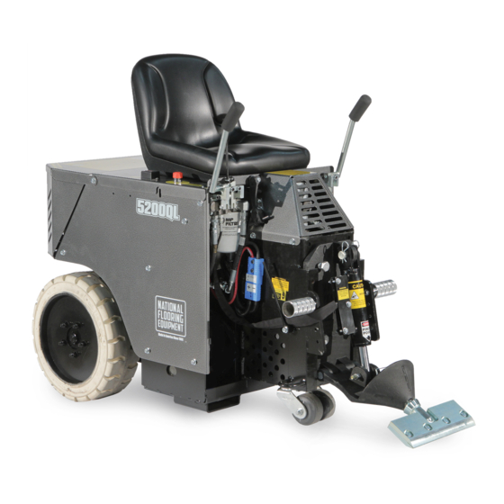
- Page 1 5200QL RIDE-ON SCRAPER OPERATING & SERVICE MANUAL Read Manual Before Operating or Servicing Machine 402228 Rev E...
- Page 2 TO PURCHASE THIS PRODUCT PLEASE CONTACT US Equipment Financing and Extended Warranties Available Discount-Equipment.com is your online resource for commercial and industrial quality parts and equipment sales. 561-964-4949 visit us on line @ www.discount-equipment.com Select an option below to find your Equipment We sell worldwide for the brands: Genie, Terex, JLG, MultiQuip, Mikasa, Essick, Whiteman, Mayco, Toro Stone, Diamond Products, Generac Magnum, Airman, Haulotte, Barreto, Power Blanket, Nifty Lift, Atlas Copco, Chicago Pneumatic, Allmand, Miller Curber, Skyjack, Lull,...
-
Page 3: Table Of Contents
Table of Contents Table of Contents ................................3 Features and Specifications ............................4 Safety ....................................5 General Rules for Safe Operation ......................... 5 Ride-On Scraper Safety Guidelines ........................6 Hydraulic Safety ..............................7 Components and Assembly ............................8 Battery Operation and Replacement ........................8 Transport ................................ -
Page 4: Features And Specifications
*Net weight includes removable weights, cutting head and transport wheels. Machine Variants Region Serial Number Power / Frequency Body Panels Slide Plate Domestic 5200QL-10XXXX 120V / 60 Hz Silver Vein Manual Lift (North America) International 5200QL-28XXXX 100V / 50/60 Hz... -
Page 5: Safety
Safety GENERAL RULES FOR SAFE OPERATION Before use, anyone operating or performing maintenance on this equipment must read and understand this manual, as well as any labels pack- aged with or attached to the machine and its components. Read the manual carefully to learn equipment applications and limitations, as well as potential hazards associated with this type of equipment. -
Page 6: Ride-On Scraper Safety Guidelines
Safety RIDE-ON SCRAPER SAFETY GUIDELINES Scraping Batteries and Chargers Do not drive machine along hills or uneven surfaces. Use caution; risk of explosive gases. The weight of the machine may become distributed differently if on Batteries generate explosive gases during normal operation. Do an uneven surface. -
Page 7: Hydraulic Safety
Safety HYDRAULIC SAFETY Maintaining a Safe Work Environment Establishing a safe work environment in and around your hydraulic equipment is extremely important. The easiest and most effective way to avoid problems is to make sure associates understand their equipment, know how to operate the machines safely, and recognize the dangers if handled carelessly. -
Page 8: Components And Assembly
Components and Assembly BATTERY OPERATION AND REPLACEMENT Blue plug - Front, 48V hook-up to motor. Gray plug - Top, 24V series hook-up to create a 48V pack. Red plugs - Rear/Right/Left, 24V access for recharging batteries either inside or outside. Blue port - 48V terminal to connect power to motor. -
Page 9: Transport
Components and Assembly Connect the charger to the blue 48V plug and to a power source. Connecting to power source starts the charging automatically. It will take 4-8 hours to charge both packs, depending on the level of discharge and available voltage. Charging is complete once the LED stays solid green. -
Page 10: Jobsite Movement
Components and Assembly JOBSITE MOVEMENT WARNING: PROVIDE BARRIERS OR SHIELDS AS NEEDED TO PROTECT OTHERS FROM DEBRIS AND MACHINE OPERATION. OPERATOR SHOULD BE AWARE OF THE PROXIMITY OF OTHERS. Taping Wheels Taping the wheels with a wide masking tape helps to prevent dirtying or damaging the floors during move-in and move-out. - Page 11 Components and Assembly save time on the job. Insert blades into the extra cutting heads before starting a job. Blade Securing Bolt Cutting Head When the blade is dull, take out the cutting head and replace it with another. Shear Point The shear point is the point where material to be removed will cut cleanly from the floor.
-
Page 12: Foot Pegs
Components and Assembly Blade Setting • Proper blade size and placement, depending on material and sub-floor type, af- Bevel Up fects performance. • For better results during difficult removal applications use a smaller blade. • Start with a narrow blade, then increase blade size to optimize cutting pass. Nar- rower blades work easier than wider blades and usually clean the floor better. -
Page 13: Operation
Operation OPERATING CONTROLS Power On Button/Key (Figure 11) Never use the Power On button/key as a method for speed control. Speed control is achieved by the hydraulic valve only. Using the On/Off switch repeatedly will cause excessive wear, causing premature failure of electrical components. Hydraulic Levers (Figure 12) Domestic International... -
Page 14: Shut-Down Procedure
Operation SHUT-DOWN PROCEDURE The machine will stop when the operator is no longer seated, or when the emergency stop is engaged. Remove blade or drop cutting head to the floor when machine is not in use. SLIDE PLATE ADJUSTMENTS AND SETTINGS Manual Lift (Figure 16) FIG. -
Page 15: Application Setup
Operation APPLICATION SETUP Ceramic (Figure 18) The slide plate should be adjusted to a low setting 1” (2.5 cm) off the floor. Use a shank blade or a shank blade with a carbide tip. Wood Slide Plate 1” Off Floor The slide plate should be adjusted to a low setting 1”... -
Page 16: Ditching
Operation Concrete Tile Ditch 1’-2’ 2”-6” Blade should be bevel up when working over concrete. Pretty much anything over con- CROSS-ROOM DITCHING Strips Blade crete works. Try different setups to see which works best. If goods come up difficult, the slide plate should be at a low setting, 1”... -
Page 17: Maintenance Schedule
Maintenance Schedule Interval After initial After initial Maintenance to be performed Daily 200 hrs 1000 hrs 2000 hrs 100 hrs 500 hrs Inspect extension cord for damage ● Check wheels, caster and wheel motors for build up; and clean ● Inspect all safety devices (e-stop, backup beeper, seat switch) ●... -
Page 18: Troubleshooting Guide
Troubleshooting Guide Problem Cause Solution Machine will not start. Seat safety switch is disengaged. Ensure operator is seated. Emergency stop (E-Stop) switch is disen- Twist E-Stop into the “POWER ON” position. gaged. Circuit breaker is in the OFF position. Verify circuit breaker is in “ON” position. 48 volt blue plugs are not connected. -
Page 19: Maintenance
Maintenance WARNING: ALWAYS DISCONNECT BATTERY BEFORE PERFORMING MAINTENANCE. MANUAL SLIDE PLATE REMOVAL WARNING: SLIDE PLATE WILL DROP TO THE FLOOR WHEN SLIDE PLATE SECURING BOLTS ARE DISENGAGED. KEEP HANDS AND FEET OUT FROM UNDERNEATH SLIDE PLATE, FAILURE TO DO SO COULD CAUSE SEVERE BODILY INJURY. Disconnect machine from power. -
Page 20: Change Hydraulic Cylinder
Maintenance CHANGE HYDRAULIC CYLINDER Disconnect machine from power. Disconnect cylinder lines. Have a container ready to catch oil from lines. Remove cylinder securing hexhead bolt from lower cutting head support. Remove clips and pin from cylinder and slide plate. Remove cylinder upper pin. Remove cylinder. -
Page 21: Change Rear Wheel
Maintenance CHANGE REAR WHEEL (FIG. 1) Jack machine up by pushing the cylinder lift forward to lower and adjust the angle of the cutting head to raise machine. Place blocks under forklift cups on the side of the machine that wheel is being changed. -
Page 22: Remove/Replace Foot Peg
Maintenance REMOVE/REPLACE FOOT PEG Insert a socket wrench into foot peg and secure bolt head. Remove nut. Remove bolt and foot peg. Replace foot peg before operating machine. Do not operate machine without foot pegs. CLEAN WHEEL MOTOR BUILD-UP Inspect the wheel motor and wheel motor hub for debris build-up (best accessed from back of machine). Remove any strands of carpet and use compressed air (not high pressure) to clean out dust or glue build-up. -
Page 23: Parts List And Diagrams
PART# DESCRIPTION PART# DESCRIPTION 1 5110-111 SEAT, RIDE-ON 8 5200QL-28-SV COVER, BATTERY, SILVER VEIN 2 5700-102 ASSEMBLY, E-STOP (5200QL-10XXXX) 1 9 403131-SV COVER, HINGED TOP, SILVER VEIN 5700-102-JA ASSEMBLY, E-STOP, JAPANESE 10 5200-603 HOSE GUIDE (5200QL-28XXXX) 11 5700-103 SWITCH, START, ASSEMBLY... - Page 24 Hub Nut 401433 Pin, Cotter 1/8 x 1.75 HOOD LEVER PART# DESCRIPTION 1 73014 1/4-20 X 1-1/2 HEXHEAD BOLT 2 5200QL-31 HOOD LEVER ONLY 3 73008 1/4-20 NYLON LOCK NUT 4 5200QL-34 REVERSE CATCH 5 73005 1/4-20 X 1/2 HEXHEAD BOLT...
- Page 25 Parts List and Diagrams FOOT PEGS ITEM PART NUMBER DESCRIPTION QTY. 402298 Bracket, Pivot, Footrest 73207 NUT, NYLOCK, 3/8-16 401999 Knob, Adjustable, 3/4" 5110-180 Peg, Foot 402460 Bolt, Shoulder, .500 x .75, 3/8-16 73263 WASHER,FLAT SAE ZINC 3/8 73238 Bolt, Flange 3/8-16x1-1/2 INSTRUCTION TUBE PART# DESCRIPTION...
- Page 26 Parts List and Diagrams ELECTRIC BOX & BATTERY CONNECTOR PART# DESCRIPTION PART# DESCRIPTION 1 5200-118-1A BOX, ELECTRICAL, ONLY 5 5700-90 RELAY, SOCKET 2 5200-118-9 CONTACTS, TERMINAL, SB175 SERIES 6 5700-91 RELAY 3 5700-106 BREAKER, CIRCUIT, 70 AMP 7 5700-104 SOLENOID 4 5200-127 TERMINAL, STRIP 402228_5200QL_RevE...
- Page 27 Parts List and Diagrams MOTOR PART# DESCRIPTION 1 72385 4 HP MOTOR 2 5200QL-1A MOTOR PLATE 3 73242 SCREW, BUTTON HEAD CAP WITH FLANGE 3/8-16 X 1 4 73210 WASHER, INTERNAL/EXTERNAL LOCK 3/8 4 5 73207 NUT, NYLOCK 3/8-16 (NOT SHOWN)
- Page 28 Parts List and Diagrams SPOOL AND HOSE SPOOL AND HOSE (DUAL LIFT) (MANUAL LIFT) PART# DESCRIPTION PART# DESCRIPTION 1 5200-261 HOSE, WHEEL MOTOR 9 5700-77 SUCTION HOSE ASSEMBLY (NOT SHOWN) 1 2 5700-72 HOSE, HYDRAULIC, 3/8 X 26, F/F 10 5700-81 SUCTION LINE (NOT SHOWN) 3 5700-76 HOSE, HYDRAULIC, 3/8 X 21, F/F...
- Page 29 Parts List and Diagrams BREATHER DIP STICK PART# DESCRIPTION 1 405291 BREATHER CAP, WITH SPLASH GUARD, 1/4 NPT 2 402989 PIPE, RELIEF VALVE, 2-1/2” 3 5110-234 COUPLER, RELIEF VALVE HOSE CLAMP ASSEMBLY PART# DESCRIPTION 1 5200-261-1A CLAMP 2 5200-261-1B BODY ONLY, CLAMP 3 73063 BOLT, HEX HEAD CAP 1/4-20X1-3/4 4 73002...
- Page 30 Parts List and Diagrams SUCTION ASSEMBLY & FILTER PART# DESCRIPTION PART# DESCRIPTION 1 5700-77 ASSEMBLY, HOSE 9 400099 HOSE, SUCTION, 1/2” X 20” W/ FITTING 2 5700-81 HOSE, SUCTION LINE 10 5110-237 FILTER, SCREEN 3 5700-67 PLUG, TANK 11 73310 SCREW, SHC, 5/16-18 X 7/8 4 70653 FITTING, 90 DEGREE...
- Page 31 Parts List and Diagrams CONTROL LEVER (MANUAL LIFT) ITEM ITEM PART NUMBER DESCRIPTION QTY. PART NUMBER DESCRIPTION QTY. 402416 Assembly, Valve Handle, Right 400034 Fitting, FF1231-06-08 73320 Bolt, Socket Head Cap 5/16-18x2 401797 Bracket, Universal, Lever 73211 Nut, Flange, Serrated, 3/8-16 401408 Spacer, Round, .323 X .625 X .675 5700-60...
- Page 32 Parts List and Diagrams MANUAL SLIDE PLATE ITEM PART NO. DESCRIPTION QTY. 400132 Bolt, Hex Head, 1/2-13 x 4, Grade 8 400296 Gasket, EPDM Foam 401429 Pin, Lower Cutting Head Support 401876 SSS, 3/8-24 x .25, Black Oxide 402410 Slide Plate, Steel, Manual Adjustment 402440 Tooling Holder, Weldment 402574...
- Page 33 PART# DESCRIPTION 1 5204 POWER PACK, EXTENDED 2 5212 CHARGER, BATTERY, 48 VOLT (5200QL-10XXXX) 404062 ASSEMBLY, QUIQ 1000 CHARGER, 5200QL, JPN (5200QL-28XXXX) FRONT WHEEL ASSEMBLY PART# DESCRIPTION 1 5110-100 TRANSPORT WHEELS 2 5110-100W CASTER ASSY, 5”, TRANSPORT WHEEL WEIGHTS ITEM NO.
- Page 34 Parts List and Diagrams 5200QL-500 QUICK LOAD BATTERY CART Item# Part# Description 405502 Caster Assembly, Swivel, 4x2, PU, 600# 405503 Caster Assy, Fixed, 4x2, PU, 600# 5200QL-500F Bolt, Carriage, 1/2-13 x 1, Clear Zinc 5200QL-501 Angle, Front, Right 5200QL-502 Angle, Front, Left...
- Page 35 Label, Emergency Stop, Japanese (5200QL-28XXXX) 402927-JA Label, Charger, QuiQ 1000, Japanese (5200QL-28XXXX) 404069 Label, QuiQ Charger, Algorithm 126 (5200QL-28XXXX) L305-JA Label, Do Not Get Charger Wet, Japanese (5200QL-28XXXX) L153 Label, Power Pack Battery L156 Label, 48 Volt L157 Label, 24 Volt...
- Page 36 TO PURCHASE THIS PRODUCT PLEASE CONTACT US Equipment Financing and Extended Warranties Available Discount-Equipment.com is your online resource for commercial and industrial quality parts and equipment sales. 561-964-4949 visit us on line @ www.discount-equipment.com Select an option below to find your Equipment We sell worldwide for the brands: Genie, Terex, JLG, MultiQuip, Mikasa, Essick, Whiteman, Mayco, Toro Stone, Diamond Products, Generac Magnum, Airman, Haulotte, Barreto, Power Blanket, Nifty Lift, Atlas Copco, Chicago Pneumatic, Allmand, Miller Curber, Skyjack, Lull,...
Need help?
Do you have a question about the 5200QL and is the answer not in the manual?
Questions and answers