
Related Manuals for National Flooring Equipment 5280-AUS


Summary of Contents for National Flooring Equipment 5280-AUS
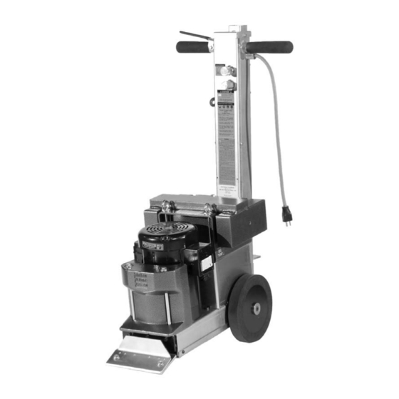
- Page 1 RevA SELF-PROPELLED SCRAPER INSTRUCTION MANUAL Caution: Read Manual Before Operating Machine 401872...
- Page 2 9250 XYLON AVE. N MINNEAPOLIS, MN 55445 MAIN: 763.315.5300 TOLL FREE: 800.245.0267 FAX: 800.648.7124 National Flooring Equipment Inc. NATIONALEQUIPMENT.COM 9250 Xylon Ave N Minneapolis, MN 55445 USA Declares that under our sole responsibility the products: 6280 COM, 6280 COM EUR, 6280 COM AUS, 6280 COM UK,...
-
Page 3: Table Of Contents
Table of Contents Table of Contents ........................................3 Features and Specifi catons ....................................4 Safety ............................................ 5-8 General Rules for Safe Operation ................................5-6 Characteristics of a Defensive Operator ............................... 6 Hydraulic Safety Tips ....................................6 Grounding ........................................7 Extension Cords ......................................7 Machine Operation ...................................... -
Page 4: Features And Specifi Catons
Features and Specifi cations FWD Hydraulic Handle Control Speed Control Dial Lifting Bail Eyebolts Saddle Weight Debris Defl ecting Front Weight Traction Wheels Quick & Easy Blade Change FEATURES Speed Control Dial- Limits maximum forward speed. Quick & Easy Blade Change- Ensuring maximum production rates. Traction Wheels- These industrial grade wheels are self-cleaning and Side Weight- 50 pound side saddle weight provides additional down disengage for loading/unloading. -
Page 5: General Rules For Safe Operation
Safety GENERAL RULES FOR SAFE OPERATION READ AND SAVE ALL INSTRUCTIONS FOR FUTURE USE. Before use, ensure operators reads and understand this manual. Read and understand labeling on machine and components. All operators must view the instruction video. Extra copies of the manual and video are avail- able. -
Page 6: Characteristics Of A Defensive Operator
Safety only identical National replacement parts. 24. STORE IDLE EQUIPMENT: When not in use, store in a dry, secured place. Keep away from children. 25. MAINTAIN LABELS AND NAMEPLATES: These carry important information. If unreadable or missing, contact National for a replace- ment. -
Page 7: Grounding
Safety spill, always check EPA, state and local regulations. 3. BURST: Whether due to improper selection or damage, a ruptured hose can cause injury. If it bursts, a worker can be burned, cut, injected or may slip and fall. 4. COUPLING-BLOW OFF: If the assembly is not properly made or installed, the coupling could come off and hit or spray a worker, possibly resulting in serious injury. -
Page 8: Extension Cords
Safety EXTENSION CORDS Grounded tools require a three wire extension cord. Double insulated tools can use either a two or three wire extension cord. As the distance from the supply outlet increases, you must use a heavier gauge extension cord. Using extension cords with inadequately sized wire causes a serious drop in voltage, resulting in loss of power and possible tool damage. -
Page 9: Machine Operation
Machine Operation TRANSPORTING Transport wheels help to eliminate damage to fl ooring and make movement of unit easier. WARNING: NEVER HAVE TRANSPORT WHEEL ASSEMBLY MOUNTED ONTO MACHINE OR WEHEELS DISENGAGED WHEN GOING UP OR DOWN A LOADING RAMP OR INCLINE. FAILURE TO DO SO COULD CAUSE MACHINE RUNAWAY, DAMAGE TO MACHINE, DAMAGE TO PROPERTY OR CAUSE SEIOUS INJURY. -
Page 10: Operating Controls
Machine Operation RAMP UNLOADING Position ramp securely to back of vehicle, making sure there is good contact (See Figure D). Position machine at the back of the truck in line with the ramp (See Figure E). Carefully move machine onto ramp leaving cutting head down (in contact with ramp surface). -
Page 11: Preparing Machine For Job
Machine Operation PREPARING MACHINE FOR JOB BLADE SETTING • Note: The 5280-AUS is designed to remove soft good materials. • Proper blade size and placement, depending on material and sub-fl oor type, af- fects performance. • The harder a job comes up, for best results, use a smaller blade. -
Page 12: Application Set-Up
Machine Operation APPLICATION SET-UP VCT TILE Never use a blade wider than the size of the tile being removed. If goods being removed still do not come up clean or machine jumps on top of goods, reduce blade size to a smaller blade until proper blade size is found or use a smaller portion of the blade. -
Page 13: Blades
Blades STANDARD BLADE (FIGURE P) This heavy duty blade is designed to remove soft goods, carpet, and vinyl fl ooring. Its .062 thickness offers fl exibility to maximize the shear point angle. PART# DESCRIPTION THICKNESS (IN.) 5” X 16” BLADE .062 5”... -
Page 14: Blades
Blades EXTRA HEAVY DUTY BLADES (FIGURE U) These extremely hard, high abrasion alloy blades are designed for tough tear up situa- tions. VCT, VAT, wood, tile, lighter ceramic, rescraping thin-set, all carpets, cork, elasto- meric coatings, rescraping rubber and urethane coatings. They hold all edges extremely well. -
Page 15: Machine Maintenance
Machine Maintenance WARNING: ALWAYS UNPLUG MACHINE BEFORE MAINTAINING. WHEEL REMOVAL Examine back of wheels (with a fl ashlight is helpful) to see if debris is built up. Keep clean from yarn build up. Unplug machine. FIG. Y Lay machine on its side. Use provided 3/16”... -
Page 16: Tank Removal
Machine Maintenance TANK REMOVAL SPEED LIMIT CONTROL KNOB Removing the tank will be necessary to repair the pump or to replace or service internal TWIST GRIP hoses. Drain tank by removing top Filler Port Cap and Drain Plug on side of machine (See Figure AA). -
Page 17: Troubleshooting
Troubleshooting Guide Problem Cause Solution No forward or reverse Belt Remove front cover plate and inspect belt. Speed control valve Inspect speed control valve, turn counter-clockwise to open valve. Motor shuts off or won’t start Push reset button located on the electric box on the motor. -
Page 18: Complete Parts List
Complete Parts List PART# DESCRIPTION PART# DESCRIPTION 1 5280-1 DRIVE CHAIN 40 STRAND 52 6280-180 MOTOR LINE 2 5280-1L MASTER LINK 53 6280-181 PRESSURE LINE 3 5280-2 AXLE SPROCKET 40 BS 13 X 3/4’’ 54 6280-182 RETURN LINE 4 5280-3 HYDRAULIC MOTOR SPROCKET 40 BS 12 X 1 1 55 6280-207 ON/OFF SWITCH... -
Page 19: Parts List And Diagrams
Parts List and Diagrams EXTERNAL PARTS PART# DESCRIPTION PART# DESCRIPTION 1 5280-111 DRIVE WHEEL 16 6280-208A SPEED CONTROL KNOB ONLY (W/O SCREW) 1 2 5280-136 BLADE COVER 17 62180 MOTOR FAN COVER 3 5280-137W BLADE WRENCH 18 62181 MOTOR FAN (NOT SHOWN) 4 5280-138 BOTTOM PLATE 19 62182... -
Page 20: Pump Parts
Parts List and Diagrams PUMP PARTS PART# DESCRIPTION PART# DESCRIPTION 1 5280-1 DRIVE CHAIN 40 STRAND 20 5280-220B HYDRAULIC MOTOR WOODRUFF KEY 1/4 X 1 1 2 5280-1L MASTER LINK 21 5280-221 HYDRAULIC MOTOR CONNECTOR 3 5280-2 AXLE SPROCKET 40 BS 13 X 3/4’’ 22 62182 CAPACITOR COVER 4 5280-3... -
Page 21: Handle Parts
Parts List and Diagrams HANDLE PARTS PART# DESCRIPTION PART# DESCRIPTION 1 5280-117 PRESSURE HOSE TO PUMP CONNECTOR 3 13 6280-170A HANDLE BAR GRIP 2 5280-167 HANDLE BODY 14 6280-180 MOTOR LINE 3 5280-167B HANDLE BODY COVER1 15 6280-181 PRESSURE LINE 4 5280-167C HANDLE SWITCH PLATE 16 6280-182... -
Page 22: Back Parts
Parts List and Diagrams BACK PARTS PART# DESCRIPTION PART# DESCRIPTION 1 5280-139C HANDLE VIBRATION ISOLATOR 5 73502 1/2 STRAIGHT STRAIN RELIEF .3376-.5685 2 5280-168 POWER CORD 6 72804 1/2 STRAIGHT CORD CONNECTOR 3 5280-172A HANDLE LEVER 7 74645 M10-16 WIZLOCK BOLT 4 5280-404 BLADE WRENCH HOLDER 8 74650... -
Page 23: Hydraulic Tank Parts
Parts List and Diagrams PART# DESCRIPTION HYDRAULIC TANK PARTS 1 5280-120 SUCTION LINE 2 5280-162 HYDRAULIC TANK BODY 3 5280-162E DRAIN PLUG/OIL LEVEL PLUG 4 6280-161D HYDRAULIC TANK FILLER CAP 5 6280-162G MAGNET (IN TANK) 6 70601 TANK MOUNTED STRAINER 7 72816 RETURN LINE ELBOW PART#... -
Page 24: Labels
Parts List and Diagrams LABELS PART# DESCRIPTION PART# DESCRIPTION 1 L37 CAUTION SHARP BLADES LABEL 9 L141 FLAG LABEL 2 L49 CAUTION CORD LABEL 10 L173A 5280 LABEL 3 L95B ON/OFF SWITCH LABEL 11 L175 NATIONAL LABEL,SMALL 4 L95C FORWARD LABEL 12 L188 CAUTION GENERAL INFO LABEL 5 L95E... -
Page 25: Accessories
Parts List and Diagrams ACCESSORIES REPLACEMENT SADDLE WEIGHT Adds and extra 45 lbs. to the drive wheels. #6280-402 Replacement Saddle Weight SWIVEL HEAD ATTACHMENT Unique Swivel Head rotates to use the second sharp edge of the blade without having to remove the blade. Designed to hold razor/scraper blades. -
Page 26: Wiring Diagram
Parts List and Diagrams 5280-AUS WIRING DIAGRAM Fax: 763-535-8255 info@nationalequipment.com... -
Page 27: Hydraulic Line Diagram
Parts List and Diagrams 5280-AUS HYDRAULIC LINE DIAGRAM www.nationalequipment.com Phone: 763-315-5300... -
Page 28: Material Safety Data Sheet
Material Safety Data Sheet (MSDS) Information CHEVRON HD 22 - 68 - HYDRAULIC FLUID PRODUCT IDENTIFICATION AND COMPANY IDENTIFICATION Product Number(S): CPS221655, CPS221658, CPS221659 CHEMTREC: (800) 424-9300 or (703) 527-3887 Synonyms: Texaco Rando HD22, Texaco Rando HD 32, Texaco Health Emergency Rando HD 46, Texaco Rando HD 68 Chevron Emergency Information Center: Located in the USA. - Page 29 Material Safety Data Sheet (MSDS) Information CHEVRON HD 22 - 68 - HYDRAULIC FLUID (CONTINUED) EXTINGUSHING MEDIA: Use water fog, foam, dry chemical or carbon dioxide (CO2) to extinguish fl ames. PROTECTION OF FIRE FIGHTERS: Fire Fighting instructions: This material will burn although it is not easily ignited. For fi res involving this material, do not enter any enclosed or confi...
- Page 30 Chevron HD 22 - 68 - hydraulic fl uid (continued) CHEVRON HD 22 - 68 - HYDRAULIC FLUID (CONTINUED) PHYSICAL AND CHEMICAL PROPERTIES Attention: The data below are typical values and do not constitute a specifi cation. Color: Yellow Physical State: Liquid Odor: Petroleum odor pH: Not applicable Vapor Pressure: <0.01 mmHg @ 37.8 C (100 F)
-
Page 31: Material Safety Data Sheet
Chevron HD 22 - 68 - hydraulic fl uid (continued) REGULATORY INFORMATION EPCRA 311/312 CATAGORIES: 1. Immediate (Acute) Health Effects: NO 2. Delayed (Chronic) Health Effects: NO 3. Fire Hazard: NO 4. Sudden Release of Pressure Hazard: NO 5. Reactivity Hazzard: NO REGULATORY LISTS SEARCHED: 01-1=IARC Group1 03=EPCRA 313... -
Page 33: Guarantee
This warranty gives you specifi c legal rights. You may also have other rights which vary from state to state. WARRANTY PERIOD The 5280-AUS Self-Propelled Walk Behind Scraper is guaranteed to be free of manufacturer defective workmanship and in quality of materi- als for a period of one year. - Page 34 9250 Xylon Avenue N • Minneapolis, MN 55445 • U.S.A. Toll-free 800-245-0267 • Phone 763-315-5300 • Fax 800-648-7124 • Fax 763-535-8255 Web Site: www.nationalequipment.com • E-Mail: info@nationalequipment.com...
Need help?
Do you have a question about the 5280-AUS and is the answer not in the manual?
Questions and answers