Table of Contents
Advertisement
Quick Links
Download this manual
See also:
Service Manual
Advertisement
Table of Contents

Subscribe to Our Youtube Channel
Related Manuals for National Flooring Equipment 550


Summary of Contents for National Flooring Equipment 550
- Page 1 ADJUSTABLE HANDLE SCRAPER INSTRUCTION MANUAL Read Manual Before Operating Machine 101713...
-
Page 3: Table Of Contents
Bearing Plate Securing Mounts ........................... 23 Wheel Parts ................................. 24 Motor ..................................24 Front Weight ................................ 25 Blade Cover ................................. 25 Blade Wrench ..............................25 Shank Holder ............................... 25 Optional Add-on Front Weight ..........................25 #550 Labels ................................. 25 Guarantee ..................................27 www.nationalequipment.com Phone: 763-315-5300... -
Page 4: Features And Specifi Cations
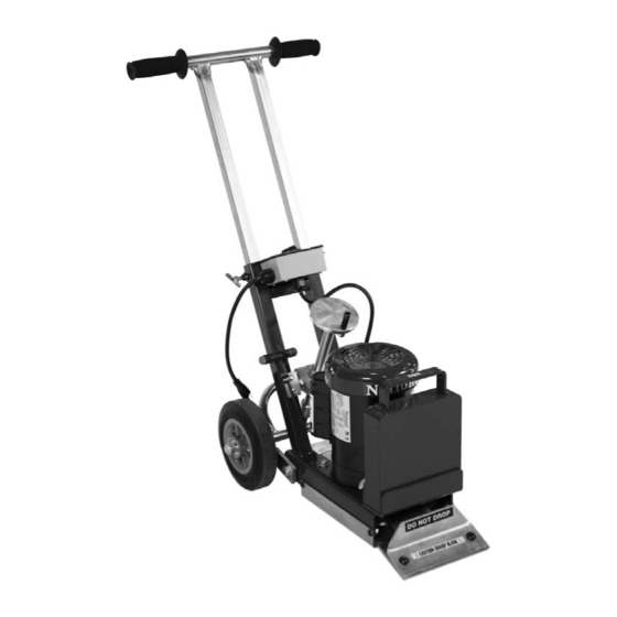
Features and Specifi cations Adjustable Handle Angle Adjustment Lift Handle Foot Bar Cutting Head FEATURES Adjustable Handle - The adjustable handle allows the operator to ing on the material being removed. This keeps the scraper “in work” adjust for comfort. and prevents fl... -
Page 5: Safety
Safety Safety GENERAL RULES FOR SAFE OPERATION READ AND SAVE ALL INSTRUCTIONS FOR FUTURE USE. Before use, ensure operators reads and understand this manual. Read and understand labeling on machine and components. All operators must view the instruction video. Extra copies of the manual and video are avail- able. -
Page 6: Characteristics Of A Defensive Operator
Safety Safety only identical National replacement parts. 24. STORE IDLE EQUIPMENT: When not in use, store in a dry, secured place. Keep away from children. 25. MAINTAIN LABELS AND NAMEPLATES: These carry important information. If unreadable or missing, contact National for a replacement. 26. -
Page 7: Grounding
Safety Safety WARNING: ELECTRICAL CORDS CAN BE HAZARDOUS. MISUSE CAN RESULT IN FIRE OR DEATH BY ELECTRICAL SHOCK. READ CAREFULLY AND FOLLOW ALL DIRECTIONS. GROUNDING Jobsite receptacles can vary. Check the voltage at different receptacles on the jobsite for a more accurate voltage reading. 15 amp GFI outlets are not recommended. FIG. - Page 8 Safety Safety GUIDELINES FOR USING EXTENSION CORDS (CONTINUED) • Keep away from water. Do not use if wet. • Inspect thoroughly before each use. DO NOT USE IF DAMAGED. • Make sure equipment is not running before disconnecting cord. • FULLY INSERT plug into outlet.
-
Page 9: Machine Operation
Machine Operation GENERAL OPERATION INFORMATION WARNING: STAY CLEAR OF BLADE WHEN MACHINE IS OPERATING. WARNING: KEEP HANDS AND FEET OUT FROM UNDER THE MACHINE. FIG. A Always wear eye protection. Keep fl ammable and fragile objects away from the equipment. Always check nuts and bolts to make sure they are tight. -
Page 10: Assembly
Machine Operation ASSEMBLY THE 550 COMES DISASSEMBLED. Loosen both handle T-bolts on the handle frame. Insert handle into handle frame (See Figure A) and adjust the handle to the desired height. Retighten T-bolts on the handle frame (See Figure A). -
Page 11: Preparing The Machine For The Job
fl at piece of 2 x 4 or something similar. Use extended socket wrench that comes with the 550 or a socket wrench with at least 3” extension to keep hand safetly away from the sharp edge of the blade. -
Page 12: Application Setup
A new sharp blade being used on wood or alike sub fl oors may work better when slightly dulled to avoid digging or gouging. • Use National Flooring Equipment replacement blades. APPLICATION SET-UP FIG. A CAUTION: BEWARE OF EXPANSION JOINTS AND FLOOR MOUNTED RECEP- TACLES OR OTHER OBSTACLES IN THE FLOOR. -
Page 13: Blade Sharpening
Machine Operation CONCRETE When working on concrete slab, normal blade position is bevel up for best performance, especially when cleaning adhesive. On occasion, bevel down gives better blade life. Test each job for best performance. GIBCRETE AND SOFT POURED FLOORING Requires blade bevel down to create a better wearing surface. -
Page 14: Blades
Blades STANDARD BLADE (FIGURE A) This heavy duty blade is designed to remove soft goods, carpet, and vinyl fl ooring. Its .062 thickness offers fl exibility to maximize the shear point angle. PART# DESCRIPTION THICKNESS (IN.) 1 135 5” X 16” BLADE .062 2 147 4”... - Page 15 Blades EXTRA HEAVY DUTY BLADES (FIGURE F) These extremely hard, high abrasion alloy blades are designed for tough tear up situations. VCT, VAT, wood, tile, lighter ceramic, re-scraping thin-set, all carpets, cork, elastomeric coatings, re-scraping rubber and urethane coatings. They hold all edges extremely well. PART# DESCRIPTION THICKNESS (IN.)
-
Page 16: Machine Maintenance
Machine Maintenance MAINTAINING EQUIPMENT WARNING: ALWAYS UNPLUG MACHINE BEFORE MAINTAINING. NEVER DISASSEMBLE THE TOOL OR TRY TO DO ANY REWIRING ON THE TOOL’S ELECTRICAL SYSTEM. FAILURE TO DO SO COULD CAUSE DAMAGE TO MACHINE OR SERIOUS INJURY. CONTACT NATIONAL FOR ALL REPAIRS. Keep equipment in good repair by adopting a regular maintenance program. -
Page 17: Troubleshooting Guide
Troubleshooting Guide Problem Cause Soulution There is no power Insuffi cient power Inspect the electrical cord for damage. Switch/Circuit Check switch and/or if the circuit breaker is tripped. Motor Noise Fan guard is malfunctioning Make sure the fan guard is not bent. Machine is hard to handle Machine is too heavy Remove the counterweight. - Page 18 COVER, BRACKET 77 74748 GROMMET, RUBBER 1/2” 35 551 HOLDER, ANGLE SHANK, OPTIONAL 78 92819 DISCONNECT, QUICK, NYLON, 16-14 36 552 SHANK, ANGLE 2-1/2X4, FOR 550 ONLY GAUGE 37 3451-2 SOLDER, 3/8 X 2” 79 L105 LABEL, ASBESTOS 38 552-2 RING...
-
Page 19: Parts List And Diagrams
Parts List and Diagrams EXTERNAL PARTS PART# DESCRIPTION PART# DESCRIPTION 1 500-15 GRIP, HANDLE (EACH) 8 550-12D WHEEL, ADJUSTMENT 2 73240 T-KNOB, 3/8-16 FRONT HANDLE 3 500-12 CORD, POWER, COMPLETE W PLUG 10 550-400 WEIGHT, FRONT COUNTER 4 550-29 WHEEL, PNEUMATIC, 2 1/2 CENTERED HUB 2... -
Page 20: Eccentric Parts
PART# DESCRIPTION 1 505-1000 COVER, BOTTOM PLATE 2 73308 BOLT, BUTTON HEAD CAP 5/16-18 X 34 3 73322 NUT, NYLOCK 5/16-18 4 550-7 FRAME, BASE 5 550-1001 HEAD, CUTTING 6 70810 ISOLATOR, VIBRATION 7 71131 BEARING, 1-1/4 ID, SBLF 206-20... -
Page 21: Switch Parts
Parts List and Diagrams PART# DESCRIPTION SWITCH PARTS 1 500-12 CORD, POWER COMPLETE W PLUG 2 550-15 BOX, ELECTRICAL W/O COVER 3 550-18 GASKET, ELECTRIC BOX 4 6280-207 SWITCH, ON/OFF 5 73240 BOLT 3/8-16 6 74433 SCREW, PHILLIPS MACHINE 10-32 X 1/2 7 73401 NUT, STRAIN RELIEF, STEEL 1/2”... -
Page 22: Adjustment Parts
Parts List and Diagrams ADJUSTMENT PARTS PART# DESCRIPTION 1 550-4 ADJUSTMENT, T-BAR 2 550-5 PLATE, BEARING 3 550-5B COLLAR, SHAFT 7/8” 4 550-6 SHAFT, ADJUSTMENT 5 550-11 ASSEMBLY, WHEEL ADJUSTMENT 6 550-12 ADJUSTMENT WHEEL W/ HANDLE ONLY 7 550-12C SPACER, SLEEVE FOR HANDLE KNOB... -
Page 23: Wheel Parts
2 500-29 WHEEL, PNEUMATIC 2 1/2 CENTERED HUB, POLYPRO 3 500-30 AXLE 4 500-30A O RINGS 5 550-4 T-BAR, ADJUSTMENT 6 62112 SHAFT COLLAR 5/8 W SET SCREW 7 73301 5/16-18 X 1/2 BUTTON HEAD SCREW 8 73302 5/16 WASHER... -
Page 24: Front Weight
Parts List and Diagrams PART# DESCRIPTION FRONT WEIGHT PARTS 1 T550-400 WEIGHT, FRONT COUNTER 2 73203 3/8 FLAT WASHER 3 73204 3/8 SPLIT LOCK WASHER 4 73209 3/8-16 X 8 1/2 HEXHEAD BOLT BLADE COVER PARTS PART# DESCRIPTION 1 5280-136 BLADE COVER 2 6280-401B BLADE WRENCH... -
Page 25: Parts List And Diagrams
Parts List and Diagrams LABELS PART# DESCRIPTION PART# DESCRIPTION 1 L13 DO NOT DROP LABEL 6 L141 MADE IN THE USA LABEL 2 L49 CAUTION CORD LABEL 7 L173C STOCK NUMBER LABEL (NOT SHOWN) 3 L51 CAUTION SHARP BLADE 8 L175 NATIONAL LABEL 4 L95B DISCONNECT POWER LABEL... -
Page 27: Guarantee
This warranty gives you specifi c legal rights. You may also have other rights which vary from state to state. WARRANTY PERIOD The 550 Adjustable Handle Scraper is guaranteed to be free of manufacturer defective workmanship and in quality of materials for a period of one year. - Page 28 9250 Xylon Avenue N • Minneapolis, MN 55445 • U.S.A. Toll-free 800-245-0267 • Phone 763-315-5300 • Fax 800-648-7124 • Fax 763-535-8255 Web Site: www.nationalequipment.com • E-Mail: info@nationalequipment.com...
Need help?
Do you have a question about the 550 and is the answer not in the manual?
Questions and answers