
Related Manuals for National Flooring Equipment 5700


Summary of Contents for National Flooring Equipment 5700
- Page 1 5700 ALL-DAY BATTERY RIDE-ON SCRAPER ® OPERATING & SERVICE MANUAL Read Manual Before Operating or Servicing Machine 401809 Rev R...
- Page 2 TO PURCHASE THIS PRODUCT PLEASE CONTACT US Equipment Financing and Extended Warranties Available Discount-Equipment.com is your online resource for commercial and industrial quality parts and equipment sales. 561-964-4949 visit us on line @ www.discount-equipment.com Select an option below to find your Equipment We sell worldwide for the brands: Genie, Terex, JLG, MultiQuip, Mikasa, Essick, Whiteman, Mayco, Toro Stone, Diamond Products, Generac Magnum, Airman, Haulotte, Barreto, Power Blanket, Nifty Lift, Atlas Copco, Chicago Pneumatic, Allmand, Miller Curber, Skyjack, Lull,...
-
Page 3: Table Of Contents
Table of Contents Table of Contents ................................3 Features and Specifications ............................4 Safety ....................................6 Safety First! ................................6 General Rules For Safe Operation ........................7 Ride-On Scraper Safety Guidelines ........................8 Hydraulic Safety ..............................9 Components and Assembly ............................10 Charger Instructions ............................ -
Page 4: Features And Specifications
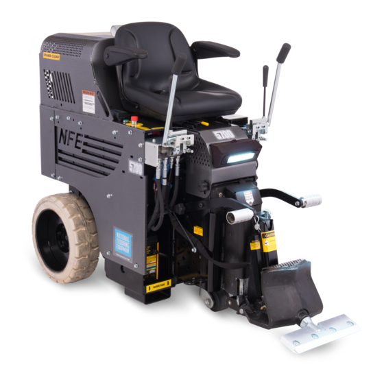
Features and Specifications Control Levers Seat Switch DC Motor Pump Compartment Headlight Adjustable Foot Rests 18” Wheels Adjustable Slide Plate Cutting Head Cylinder Lift Onboard Battery Charger Debris Deflector Forklift Cups Removable Swivel Cutting Head FEATURES Seat Switch - Ensures the machine will not function without someone DC Motor Pump Compartment - Provides easy access to the motor in the operator seat. - Page 5 (127 cm) (2.98 kW) dB(A)** 63” (160 cm) 2,198 lbs (997 kg) 2,430 lbs (1,102 kg) (5700-18XXXX Only) (Dual Lift) (Dual Lift) (Dual Lift) *Weight includes removable weights, cutting head and transport wheels. **Hearing protection is strongly recommended. Machine Variants...
-
Page 6: Safety
Safety SAFETY FIRST! Look for the safety alert symbol. This symbol is used throughout the manual and on the labels of the machine to warn of the possibility of personal injury. Read these instructions carefully. It is essential that you read these instructions before you attempt to operate the machine. Identifies an immediate hazard which, if not avoided, will result in death DANGER or serious injury. -
Page 7: General Rules For Safe Operation
Safety GENERAL RULES FOR SAFE OPERATION Before use, anyone operating or performing maintenance on this equipment must read and understand this manual, as well as any labels pack- aged with or attached to the machine and its components. Read the manual carefully to learn equipment applications and limitations, as well as potential hazards associated with this type of equipment. -
Page 8: Ride-On Scraper Safety Guidelines
Safety RIDE-ON SCRAPER SAFETY GUIDELINES Scraping Charger Operation Do not drive machine along hills or uneven surfaces. Ensure proper use of charger. The weight of the machine may become distributed differently if on • Once connected and plugged into AC power, the LED will in- an uneven surface. -
Page 9: Hydraulic Safety
Safety HYDRAULIC SAFETY Maintaining a Safe Work Environment Establishing a safe work environment in and around your hydraulic equipment is extremely important. The easiest and most effective way to avoid problems is to make sure associates understand their equipment, know how to operate the machines safely, and recognize the dangers if handled carelessly. -
Page 10: Components And Assembly
Components and Assembly CHARGER INSTRUCTIONS See Ride-On Safety Guidelines for charger safety and instructions. Before making AC connections, refer to the requirements on the charger ID label. This battery charger must be grounded to reduce the risk of electric shock. Chargers are equipped with a grounding type plug. -
Page 11: Transport
Components and Assembly TRANSPORT • Secure machine with ratchet straps during transport. Proper securing straps need to be rated at least twice the weight of the machine. • Chock wheels to keep machine from rolling, but do not use them on their own. •... -
Page 12: Cutting Head And Blades
Components and Assembly Transport Wheels The front wheel assembly is included and very helpful when moving a machine around on a jobsite or loading a machine that is not on a pallet. It allows machine stability and safe transportation over most surfaces. It is quick and easy to attach or detach. Raise slide plate so the bottom of the slide plate is higher or even with the bottom of the guide channels, 6”-8”... -
Page 13: Foot Pegs
Components and Assembly Swivel Head Blade Securing Bolt Cutting Head The swivel head keeps the blade in contact with the floor even when the floor is uneven. When using a flat blade, turning the head over 180° provides another sharp edge on the blade without having to replace the blade. -
Page 14: Operation
Operation OPERATING CONTROLS Power On Button/Key (Figure 12) Never use the Power On button/key as a method for speed control. Speed control is achieved by the hydraulic valve only. Using the On/Off switch repeatedly will cause excessive wear and premature failure of electrical components. Hydraulic Levers (Figure 13) International Domestic... -
Page 15: Shut-Down Procedure
Operation SHUT-DOWN PROCEDURE The machine will stop when the operator is no longer seated, or when the emergency stop is engaged. Remove blade or drop cutting head to the floor when machine is not in use. SLIDE PLATE ADJUSTMENT AND SETTINGS Manual Lift (Figure 17) WHEN ADJUSTING THE SLIDE PLATE, KEEP FEET AND WARNING:... -
Page 16: Application Setup
Operation APPLICATION SETUP Ceramic (Figure 20) The slide plate should be adjusted to a low setting 1” (2.5 cm) off the floor. Use a shank blade or a shank blade with a carbide tip. Wood Slide Plate 1” Off Floor The slide plate should be adjusted to a low setting 1”... -
Page 17: Ditching
Operation Concrete Tile Ditch 1’-2’ 2”-6” Blade should be bevel up when working over concrete. Pretty much anything over con- CROSS-ROOM DITCHING Strips Blade crete works. Try different setups to see which works best. If goods come up difficult, the slide plate should be at a low setting, 1”... -
Page 18: Maintenance Schedule
Maintenance Schedule Interval After initial After initial Maintenance to be performed Daily 200 hrs 1000 hrs 2000 hrs 100 hrs 500 hrs Inspect extension cord for damage ● Check wheels, caster and wheel motors for build up; and clean ● Inspect all safety devices (e-stop, backup beeper, seat switch) ●... -
Page 19: Troubleshooting Guide
Troubleshooting Guide Problem Cause Solution Machine will not start. Seat safety switch is disengaged. Ensure operator is seated. Emergency stop (E-Stop) switch is disen- Twist E-Stop so that it is in the “POWER ON” gaged. position. Circuit breaker is in the “OFF” position. Verify circuit breaker is in “ON”... -
Page 20: Maintenance
Maintenance WARNING: ALWAYS DISCONNECT BATTERY BEFORE PERFORMING MAINTENANCE. MANUAL SLIDE PLATE REMOVAL WARNING: SLIDE PLATE WILL DROP TO THE FLOOR WHEN SLIDE PLATE SECURING BOLTS ARE DISENGAGED. KEEP HANDS AND FEET OUT FROM UNDERNEATH SLIDE PLATE, FAILURE TO DO SO COULD CAUSE SEVERE BODILY INJURY. Disconnect machine from power. -
Page 21: Check Hydraulic Oil Level
Maintenance CHECK HYDRAULIC OIL LEVEL Check fluid level in the fill hole on the right side of the frame, in front of the rear wheel. Remove filler plug. Oil should be visible 1” below hole. Reinsert plug. HYDRAULIC OIL CHANGE OUT Disconnect machine from power (charger or battery). -
Page 22: Change Wheel Motor
Maintenance Take notice of angle of valve fittings. Remove two 5/16-18” bolts securing valve body. CHANGE WHEEL MOTOR Disconnect machine from power. Block up machine to remove wheel. Remove wheel. FIG. 1 Remove oil lines from wheel motor. A small amount of oil will run out of the lines. Drain into a container. -
Page 23: Seat Replacement
Maintenance Raise motor; disconnect electrical connections. Remove and replace motor. SEAT REPLACEMENT Rotate hood to bumper stops. Remove four nuts securing seat rails. Replace seat; screw on nuts. REMOVE/REPLACE FOOT PEG Insert a socket wrench into foot peg and secure bolt head. Remove nut. -
Page 24: Parts List And Diagrams
(5700-15XXXX ONLY) (NOT SHOWN) 404303-BLK SHROUD WELDMENT, LOWER WRAP, 401561-G PANEL, SIDE, LEFT, GREEN BOLTED HINGE, BLACK (5700-12XXXX ONLY - NOT SHOWN) (5700-30XXXX ONLY) 401561-O PANEL, SIDE, LEFT, ORANGE 9 403132-SV HOOD, RIDE-ON, SILVER VEIN (5700-15XXXX ONLY - NOT SHOWN) - Page 25 Parts List and Diagrams REAR WHEEL ASSEMBLY ITEM PART NUMBER DESCRIPTION QTY. 400133 Motor, Wheel, Hydraulic, 10mm 73047 Key, Woodruff 5/16 x 1 73402 Nut, Nylock 1/2-13 5110-117 Wheel, Hub 73430 Nut, NyLock 1/2-20 5110-405 Wheel, Rim and Tire, 18" 5110-117-2 Hub Nut 401433...
- Page 26 Parts List and Diagrams HOOD BUMPER ASSEMBLY PART# DESCRIPTION 1 73020 BOLT, WIZLOCK 1/4-20X5/8 2 5600-66 BUMPER, HOOD 3 73002 WASHER, SPLIT LOCK 1/4 WEIGHTS PART# DESCRIPTION 1 74854 WEIGHT, POCKET, CAST, RIDE ON 2 73424 WASHER, FLAT, ZINC SAE 5/8 3 73403 WASHER, SPLIT LOCK 1/2 4 73414...
- Page 27 DESCRIPTION PART# DESCRIPTION 1 5200-261 HOSE, WHEEL MOTOR 5 N/A SEE CONTROL LEVER PARTS (MANUAL 2 5700-72 HOSE, HYDRAULIC, 3/8 X 21, F/F LIFT) 3 5700-76 HOSE, HYDRAULIC, 3/8 X 26, F/F 6 N/A SEE GEAR PUMP ASSEMBLY 4 N/A...
- Page 28 Parts List and Diagrams SUCTION ASSEMBLY PART# DESCRIPTION PART# DESCRIPTION 1 5700-77 ASSEMBLY, HOSE 7 70655 PIPE, MALE, 10” X 3/4 2 5700-81 HOSE, SUCTION LINE 8 5700-93 GASKET 3 5700-67 PLUG, TANK 9 400099 HOSE, SUCTION, 1/2” X 20” W/ FITTING...
- Page 29 Parts List and Diagrams GEAR PUMP ASSEMBLY PART# DESCRIPTION 1 70905-D4 PUMP, DOUBLE, MARZOCCHI 70905-D5 PUMP, DOUBLE, MARZOCCHI (5700-18XXXX ONLY) 2 5200-1G GASKET, PUMP 3 72816 FITTING, ELBOW, 90 DEGREE, 3/8” 4 6280-118 FITTING, SUCTION HOSE TO PUMP 5 73263...
- Page 30 Bolt, Socket Head Cap 5/16-18x2 401797 Bracket, Universal, Lever 401408 Spacer, Round, .323 X .625 X .675 400137 Fitting, 1/2 - 1/4, JIC 5700-60 Handle, Valve Adjustment 73027 Bolt, Wizlock, 1/4-20 X 3/4 401604 Bushing, Lever, Hydro Valve 73211 Nut, Flange, Serrated, 3/8-16...
- Page 31 Bolt, Socket Head Cap 5/16-18x2 401797 Bracket, Universal, Lever 73211 Nut, Flange, Serrated, 3/8-16 401408 Spacer, Round, .323 X .625 X .675 5700-60 Handle, Valve Adjustment 73027 Bolt, Wizlock, 1/4-20 X 3/4 73322 Nut, Nyloc, 5/16-18 401604 Bushing, Lever, Hydro Valve...
- Page 32 Parts List and Diagrams DUAL SLIDE PLATE ITEM PART NO. DESCRIPTION QTY. 400132 Bolt, Hex Head, 1/2-13 x 4, Grade 8 400296 Gasket, EPDM Foam 401429 Pin, Lower Cutting Head Support 401876 SSS, 3/8-24 x .25, Black Oxide 402423 Housing, Hydraulic Adjustment, Wldt 402432 Slide Plate, Hydraulic Adjustment, Wldt 402440...
- Page 33 Parts List and Diagrams MANUAL SLIDE PLATE ITEM PART NO. DESCRIPTION QTY. 400132 Bolt, Hex Head, 1/2-13 x 4, Grade 8 400296 Gasket, EPDM Foam 401429 Pin, Lower Cutting Head Support 401876 SSS, 3/8-24 x .25, Black Oxide 402410 Slide Plate, Steel, Manual Adjustment 402440 Tooling Holder, Weldment 402574...
- Page 34 Parts List and Diagrams ELECTRICAL BOX ASSEMBLY PART# DESCRIPTION 1 5200-118-8 CONNECTOR, BLUE 48V BATTERY 2 5700-100 WIRE SET (NOT SHOWN) 3 5700-104 SOLENOID 4 5700-106 BREAKER, CIRCUIT, 70 AMP 5 5700-85 COVER, TERMINAL STRIP 6 403129 HARNESS, MAIN 7 71703...
- Page 35 Parts List and Diagrams CHARGER ASSEMBLY 5700-10XXXX 5700-12XXXX 5700-16XXXX ITEM PART DESCRIPTION QTY. Item 5700-11XXXX NUMBER 5700-17XXXX 5700-13XXXX 5700-20XXXX 5700-28XXXX Description Qty. 5700-15XXXX Part No. 5700-18XXXX 5700-30XXXX Part No. 5700-23XXXX Plate, Mounting, High Frequency 402588 Assembly, Delta-Q Charger Replacement, 1500W, 108-...
- Page 36 Parts List and Diagrams POWER CONTROLS (DOMESTIC) PART# DESCRIPTION 1 5700-103 SWITCH, START, ASSEMBLY 72451* CONTACT, NORMALLY OPEN 72454 PUSH BUTTON, GREEN 72456* COLLAR, BODY MOUNTING 2 5700-102 ASSEMBLY, E-STOP 72452* CONTACT, NORMALLY CLOSED 72453 PUSH BUTTON, RED 72456* COLLAR, BODY MOUNTING...
- Page 37 Parts List and Diagrams SEAT ASSEMBLY PART# DESCRIPTION 1 401631 ADJUSTER, FORE/AFT, SEAT 2 5110-111 SEAT, RIDE-ON 3 400321 ARM RESTS, KIT FOR SEAT 4 73322 NUT, NYLOC, 5/16-18 (NOT SHOWN) SEAT SWITCH PART# DESCRIPTION 1 5110-207 SWITCH, SEAT SEAT HARNESS PART# DESCRIPTION 1 403128...
- Page 38 TRANSPORT WHEELS 2 5110-100W CASTER ASSY, 5”, TRANSPORT WHEEL TELEMATICS OPTIONS Item Option A Option B Description Qty. 5700-12XXXX 5700-23XXXX 406277 Module, Telematics, M7MG Lite 406278 Mount Kit, Telematics, M7MG Lite Kit, Telematics, TU600 407260 Harness, Telematics Option A, Battery...
- Page 39 L311-2* LABEL, BATTERY 407385 LABEL, QR CODE, MANUALS, 3X1.5”, JAPAN L33B LABEL, CAUTION MOVING PART (5700-16XXXX, -28XXXX, -30XXXX ONLY) 1 402149 LABEL, FORKLIFT POINT *Not shown **Kit includes Items 2-24. Suffix (-XX) denotes language: None=English; -FR=French; -NL=Dutch; -DE=German; -JA=Japanese. 401809_5700_RevR...
-
Page 40: Wiring Diagrams
Wiring Diagrams 5700/7700 PG 1 PRIMARY SYSTEM WIRING DIAGRAM MAIN BATT BATTERY BREAKER BANK 4-RED (5) 4-RED (6) LINE 16-RED TO HO BATTERY LOAD BANK 4-BLK (1) 4-BLK (2) ESTOP TO C2 C10-3 16-YEL 16-RED CONTROLS CONTR MOTOR CONTACTOR 16-RED... - Page 41 THE INFORMATION CONTAINED IN THIS 407246 6/24/2022 2361 DWG. NO. ADDED TELEMATICS OPTION B DRAWING IS THE SOLE PROPERTY OF NATIONAL FLOORING EQUIPMENT INC. ANY REPRODUCTION IN PART OR IN SIZE WHOLE WITHOUT THE WRITTEN SHEET 1 OF 5 PERMISSION OF NATIONAL FLOORING EQUIPMENT INC PROHIBITED.
- Page 42 Wiring Diagrams 5700/7700 CONTROLS WIRING DIAGRAM PG 3 TO HOOD TO M MAIN RELAY 16-YEL 16-YEL LVI OUT 16-WHT 16-WHT ON SIGNAL JUMPER BAR 16-BLU 16-BLU SFTY OUT A 16-BLU CTRL 16-ORG 16-ORG CTRL B TO HOOD C10-2 16-RED 16-RED...
- Page 43 PROPRIETARY AND CONFIDENTIAL THE INFORMATION CONTAINED IN THIS 407246 DWG. NO. DRAWING IS THE SOLE PROPERTY OF NATIONAL FLOORING EQUIPMENT INC. ANY REPRODUCTION IN PART OR IN SIZE WHOLE WITHOUT THE WRITTEN SHEET 2 OF 5 PERMISSION OF NATIONAL FLOORING EQUIPMENT INC PROHIBITED.
- Page 44 Wiring Diagrams 5700/7700 HOOD ACCESSORIES WIRING DIAGRAM PG 5 LIGHT J400 TO MAIN CONT SWITCH J431 16-ORG-430 S-430 18-ORG-431 MOTOR RLY T-F3 18-RED WORK J423 T-M1 16-BLK-422 S-422 18-BLK-423 18-BLK LIGHT CTRL BUS - TELEMATICS OPTIONS A & B 16-WHT-005...
- Page 45 PROPRIETARY AND CONFIDENTIAL THE INFORMATION CONTAINED IN THIS 407246 DWG. NO. DRAWING IS THE SOLE PROPERTY OF NATIONAL FLOORING EQUIPMENT INC. ANY REPRODUCTION IN PART OR IN SIZE WHOLE WITHOUT THE WRITTEN SHEET 3 OF 5 PERMISSION OF NATIONAL FLOORING EQUIPMENT INC PROHIBITED.
- Page 46 Wiring Diagrams 5700/7700 TELEMATICS OPTION B PG 7 E-STOP FUSE CONTACT B HOLDER 18-RED-100 S-100 16-RED-101 BATT PWR S-102 16-RED-102 P150 TELE. UNIT 18-RED-103 18-RED-104 16-BLK-002 16-BLK-002 18-BRN-150 16-WHT-005 16-WHT-005 18-PUR-112 18-YEL-200 J110 TELE. RELAY 18-RED-104 111 16-PUR-111 16-PUR-110 S-110...
- Page 47 PROPRIETARY AND CONFIDENTIAL THE INFORMATION CONTAINED IN THIS 407246 DWG. NO. DRAWING IS THE SOLE PROPERTY OF NATIONAL FLOORING EQUIPMENT INC. ANY REPRODUCTION IN PART OR IN SIZE WHOLE WITHOUT THE WRITTEN SHEET 4 OF 5 PERMISSION OF NATIONAL FLOORING EQUIPMENT INC PROHIBITED.
- Page 48 Wiring Diagrams 5700/7700 BATTERY BANK LAYOUT DIAGRAM PG 9 BATTERY #12 BATTERY #6 BATTERY #11 BATTERY #5 BATTERY #3 BATTERY #9 BATTERY #2 BATTERY #8 BATTERY #7 BATTERY #10 BATTERY #1 BATTERY #4 NOTE: BATT #1 IS TYPICALLY ROTATED 180 FROM DEPICTION...
- Page 49 TO PURCHASE THIS PRODUCT PLEASE CONTACT US Equipment Financing and Extended Warranties Available Discount-Equipment.com is your online resource for commercial and industrial quality parts and equipment sales. 561-964-4949 visit us on line @ www.discount-equipment.com Select an option below to find your Equipment We sell worldwide for the brands: Genie, Terex, JLG, MultiQuip, Mikasa, Essick, Whiteman, Mayco, Toro Stone, Diamond Products, Generac Magnum, Airman, Haulotte, Barreto, Power Blanket, Nifty Lift, Atlas Copco, Chicago Pneumatic, Allmand, Miller Curber, Skyjack, Lull,...
Need help?
Do you have a question about the 5700 and is the answer not in the manual?
Questions and answers