
Related Manuals for National Flooring Equipment 4230


Summary of Contents for National Flooring Equipment 4230
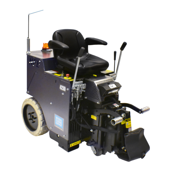
- Page 1 4230 ELECTRIC RIDE-ON SCRAPER SERVICE MANUAL Read Manual Before Servicing Machine 404733 Rev A...
-
Page 3: Table Of Contents
Table of Contents Table of Contents ................................3 Specifications ................................4 Safety ....................................5 General Rules For Safe Operation ........................5 Ride-On Scraper Safety Guidelines ........................6 Hydraulic Safety ..............................7 Recommended Electrical Practices ........................8 Maintenance Schedule ..............................10 Troubleshooting Guide ..............................11 Maintenance ................................. -
Page 4: Specifications
Up to 71 ft/min 24 hours Twin 1.5 HP motors 94-97 dB(A) (Up to 21.6 m/min) Machine Variants Region Serial Number Power / Frequency Body Panels Slide Plate Europe 4230-11XXXX 230V / 50 Hz Silver Vein Dual Lift Dual Lift Manual Lift... -
Page 5: Safety
Read the manual carefully to learn equipment applications and limitations, as well as potential hazards associated with this type of equipment. Keep manual near machine at all times. If your manual is lost or damaged, contact National Flooring Equipment (NFE) for a replacement. Personal Maintenance &... -
Page 6: Ride-On Scraper Safety Guidelines
Safety RIDE-ON SCRAPER SAFETY GUIDELINES Scraping Do not drive machine along hills or uneven surfaces. The weight of the machine may become distributed differently if on an uneven surface. Too much of an angle could make the machine unsafe or cause it to tip over. Always keep the front of the machine facing downward while traveling up or down ramps or inclines. -
Page 7: Hydraulic Safety
Safety HYDRAULIC SAFETY Maintaining a Safe Work Environment Establishing a safe work environment in and around your hydraulic equipment is extremely important. The easiest and most effective way to avoid problems is to make sure associates understand their equipment, know how to operate the machines safely, and recognize the dangers if handled carelessly. -
Page 8: Recommended Electrical Practices
Safety RECOMMENDED ELECTRICAL PRACTICES CAUTION: ALWAYS FOLLOW APPLICABLE ELECTRICAL CODES, STANDARDS AND/OR REGULATIONS. CONSULT YOUR LOCAL ELECTRICAL AUTHORITY OR A LICENSED ELECTRICIAN BEFORE ATTEMPTING TO MODIFY AN ELECTRICAL INSTALLATION. ENSURE THAT CIRCUIT AND GROUND FAULT PROTECTION DEVICES AND ALL OTHER ELECTRICAL SAFETY EQUIPMENT ARE FUNCTIONING PROPERLY. - Page 9 Safety RECOMMENDED ELECTRICAL PRACTICES—CONTINUED Single-Phase Equipment 100V Supply 20ft (6m) 40ft (12m) 60ft (20m) 80ft (25m) 120V Supply 25ft (7.5m) 50ft (15m) 75ft (25m) 100ft (30m) Length 230V Supply 50ft (15m) 100ft (30m) 150ft (45m) 200ft (60m) Max Amps Minimum Wire Size 16 AWG (1.5mm 16 AWG (1.5mm 14 AWG (2.5mm...
-
Page 10: Maintenance Schedule
Maintenance Schedule Interval After initial After initial Maintenance to be performed Daily 200 hrs 1000 hrs 2000 hrs 100 hrs 500 hrs Inspect extension cord for damage. ● Check wheels, caster and wheel motors for build up; and clean. ● Inspect all safety devices (e-stop, backup beeper, seat switch). -
Page 11: Troubleshooting Guide
Troubleshooting Guide Problem Cause Solution Machine will not start. Seat safety switch is disengaged. Ensure operator is seated. Emergency stop switch is pushed. Release emergency stop switch. Key switch did not fully engage. Turn the key fully and long enough for the motors to begin running. -
Page 12: Maintenance
Maintenance WARNING: ALWAYS DISCONNECT MACHINE FROM POWER BEFORE PERFORMING MAINTENANCE. MANUAL SLIDE PLATE REMOVAL Disconnect machine from power. Remove slide plate pin. Remove cutting head bolt Remove cylinder from slide plate. Remove slide plate. WARNING: SLIDE PLATE WILL DROP TO THE FLOOR WHEN SLIDE PLATE SECURING BOLTS ARE DISENGAGED. KEEP HANDS AND FEET OUT FROM UNDERNEATH SLIDE PLATE, FAILURE TO DO SO COULD CAUSE SEVERE BODILY INJURY. -
Page 13: Hydraulic Oil Change Out
Maintenance HYDRAULIC OIL CHANGE OUT Disconnect machine from power. Drain fluid by removing the drain plug from side of tank. This unit contains 6 gallons (22.7 liters) of fluid. Ensure the container size is ad- equate to catch fluid. Replace drain plug. Remove filler plug. -
Page 14: Change Pump
Maintenance CHANGE PUMP Disconnect machine from power. Follow Remove Front and Rear Hoods procedure to gain access to pump. Disconnect hydraulic lines. Remove two 5/16” pump securing bolts. Remove pump by pulling pump straight out from pump motor. NOTE: Pump-to-motor alignment is critical for effective operation of machine. FIG. -
Page 15: Change Caster
Maintenance Raise cylinder to raise machine off of blocks. Remove blocks and lower machine. Repeat on other side if necessary. CHANGE CASTER Keep clean and free of debris; ensure it can move freely. Before replacing caster, try adding grease to zerk fitting to see if this helps caster move more freely. To remove caster, machine will need to be raised. -
Page 16: Parts List And Diagrams
Parts List and Diagrams EXTERNAL PARTS PART# DESCRIPTION PART# DESCRIPTION 1 5200QL-25-SV PANEL, RIGHT, SILVER VEIN 5 5110-215 GUIDE, EXTENSION CORD 2 5200QL-26-SV PANEL, LEFT, SILVER VEIN (NOT SHOWN) 1 6 5110-216 CORD GUIDE BRACKET 3 402995-SV HOOD, FRONT, RAISED W/ DOGHOUSE, 7 5200QL-27 MAIN BASE (NOT SHOWN) SILVER VEIN... - Page 17 Parts List and Diagrams CASTER WHEEL ASSEMBLY ITEM PART NUMBER DESCRIPTION QTY. 5200-194 Caster, Double Gray 73403 Washer, Split lock 1/2 73424 Washer, Flat, Zinc SAE 1/2 73427 Bolt, Hex Head Cap 1/2-13x1-1/2 REAR WHEEL ASSEMBLY (2X) ITEM PART NUMBER DESCRIPTION QTY.
- Page 18 Parts List and Diagrams FOOT PEG ASSEMBLY (2X) ITEM PART NUMBER DESCRIPTION QTY. 402298 Bracket, Pivot, Footrest 73207 NUT, NYLOCK, 3/8-16 401999 Knob, Adjustable, 3/4" 5110-180 Peg, Foot 402460 Bolt, Shoulder, .500 x .75, 3/8-16 73263 WASHER,FLAT SAE ZINC 3/8 73238 Bolt, Flange 3/8-16x1-1/2 SEAT ASSEMBLY...
- Page 19 Parts List and Diagrams INSTRUCTION TUBE PART# DESCRIPTION 1 70602 TUBE, INSTRUCTION MANUAL 2 70603 CAP, INSTRUCTION TUBE 3 74425 NUT, KEPS LOCK 10/32 REAR HOOD CATCH ASSEMBLY REAR HOOD CATCH ASSEMBLY ITEM PART NUMBER DESCRIPTION QTY. 73008 Nut, Hex, Nylon Insert, 1/4-20 73021 Bolt, Hex Head Cap 1/4-20x2-1/4 73091...
- Page 20 Parts List and Diagrams HOSE CLAMP ASSEMBLY (2X) PART# DESCRIPTION Hose Clamp Assembly 1 5200-261-1A CLAMP 2 5200-261-1B BODY ONLY, CLAMP 3 73002 WASHER, SPLIT LOCK 1/4 4 73063 BOLT, HEX HEAD CAP 1/4-20X1-3/4 5 73091 WASHER, FLAT, ZINC, SAE 1/4 ITEM PART NUMBER DESCRIPTION...
- Page 21 Parts List and Diagrams MOTOR AND PUMP ASSEMBLY (2X) ITEM NO. ITEM PART NUMBER DESCRIPTION QTY. 73201 Screw, Hex Head Cap, 3/8-16 x 1 73351 Washer, Flat, 5/16, SAE 73303 Washer, Split Lock, 5/16 73307 Screw, Hex Head Cap, 5/16-18x1 5110-200 Mount, Motor 72366...
- Page 22 Parts List and Diagrams SPOOL AND HOSE PARTS SPOOL AND HOSE PARTS (DUAL LIFT) (MANUAL LIFT) PART# DESCRIPTION PART# DESCRIPTION 1 5200-261 HOSE, HYDRAULIC, 3/8 X 40, F/45F 7 N/A SEE GEAR PUMP ASSEMBLY 2 5700-72 HOSE, HYDRAULIC, 3/8 X 21, F/F 8 5110-114-2 FITTING, WHEEL MOTOR (NOT SHOWN) 4 3 5700-75...
- Page 23 Parts List and Diagrams SUCTION ASSEMBLY & FILTER PART# DESCRIPTION PART# DESCRIPTION 1 5700-77 HOSE, HYDRAULIC, 1/2 X 13.5, M/F 10 5110-237 FILTER, SCREEN 2 5700-81 HOSE, HYDRAULIC, 1/2 X 14.5, M/F 11 73311 SCREW, SOCKET HEAD CAP, 5/16-18X1 3 5700-67 PLUG, TANK (NOT SHOWN) 4 70654...
- Page 24 Parts List and Diagrams CONTROL LEVER (DUAL LIFT) ITEM ITEM PART NUMBER DESCRIPTION QTY. PART NUMBER DESCRIPTION QTY. 402416 Assembly, Valve Handle, Right 400034 Fitting, FF1231-06-08 73320 Bolt, Socket Head Cap 5/16-18x2 401797 Bracket, Universal, Lever 401408 Spacer, Round, .323 X .625 X .675 400137 Fitting, 1/2 - 1/4, JIC 5700-60...
- Page 25 Parts List and Diagrams CONTROL LEVER (MANUAL LIFT) ITEM ITEM PART NUMBER DESCRIPTION QTY. PART NUMBER DESCRIPTION QTY. 400034 Fitting, FF1231-06-08 402416 Assembly, Valve Handle, Right 73320 Bolt, Socket Head Cap 5/16-18x2 401797 Bracket, Universal, Lever 73211 Nut, Flange, Serrated, 3/8-16 401408 Spacer, Round, .323 X .625 X .675 5700-60...
- Page 26 Parts List and Diagrams DUAL SLIDE PLATE ITEM PART NUMBER DESCRIPTION QTY. *-NOT SHOWN 400132 Bolt, Hex Head, 1/2-13 x 4, Grade 8 400296* Gasket, EPDM Foam 401429 Pin, Lower Cutting Head Support 401876 SSS, 3/8-24 x .25, Black Oxide 402423 Housing, Hydraulic Adjustment, Wldt 402432...
- Page 27 Parts List and Diagrams MANUAL SLIDE PLATE ITEM PART NUMBER DESCRIPTION QTY. Bolt, Hex Head, 1/2-13 x 400132 4, Grade 8 400296* Gasket, EPDM Foam Pin, Lower Cutting Head 401429 Support SSS, 3/8-24 x .25, Black 401876 Oxide Slide Plate, Steel, Manual 402410 Adjustment 402440...
- Page 28 Parts List and Diagrams 404696 CONTROL PANEL 18 4X 8 2X 19 2X ITEM PART ITEM PART DESCRIPTION QTY. DESCRIPTION QTY. NUMBER NUMBER 404586 Electrical Box, Modified, Ride-on, Electric 403279 Screw, Button Head Cap, M5-0.8 x 12, Clear Zinc 404684 DIN Rail, Top Hat, 35mm x 7.5mm x 240mm 403075 Screw, Phillips Pan Head, M4-0.7x10, Clear Zinc...
- Page 29 Parts List and Diagrams REAR SHROUD HARNESS PART# DESCRIPTION 1 404671 HARNESS, REAR SHROUD SIDE PANEL HARNESS PART# DESCRIPTION 1 404672 HARNESS, SIDE PANEL SEAT HARNESS PART# DESCRIPTION 1 404673 HARNESS, SEAT...
- Page 30 Parts List and Diagrams POWER CONTROLS PART# DESCRIPTION 1 72455 SWITCH, KEYED 2 72451* CONTACT, NORMALLY OPEN 3 72456* COLLAR, BODY MOUNTING 4 5700-102 ASSEMBLY, E-STOP 72452* CONTACT, NORMALLY CLOSED 72453 PUSH BUTTON, RED 72456* COLLAR, BODY MOUNTING 5700-102D PLATE, EMERGENCY STOP *NOT SHOWN HOUR METER PART#...
- Page 31 Parts List and Diagrams 4230 Worklight Assembly 404734 HEADLIGHT ASSEMBLY ITEM PART NUMBER DESCRIPTION QTY. 403976 Switch, Rocker, SP, 14V, 16A ITEM PART NUMBER DESCRIPTION QTY. 404037 Shroud, Worklight, Rider 403976 Switch, Rocker, SP, 14V, 16 A 404037 Shroud, Worklight, Rider, Cinq Mille 404041 Light, Work, 6”x2”, Flush, 18W...
- Page 32 6 L223* LABEL, PATENT 15 402376 LABEL, RIDE-ON LIFT 7 L33B LABEL, CAUTION MOVING PART 16 404666* LABEL, CE, 4230, 220V, 50 HZ 8 L33C* LABEL, INSTRUCTION MANUAL 17 402045* LABEL, HI VOLTAGE WARN 9 402149 LABEL, FORKLIFT POINT 18 L142*...
- Page 33 Parts List and Diagrams 4230 Wiring Diagram Control Panel 230V SOURCE U1 - EMI FILTER T-F21 T-F22 12-BLU-#4 TERMINAL BLOCK JUMPER LINE LOAD T-F11 T-F12 12-BRN-#3 T-FM1 T-F1 12-BLU-#8 12-GRN-#1 12-BRN-#9 12-BRN-#7 T-R1 T-R2 12-GRN-#2 GROUND 2.5mm-BRN 2.5mm-BLU MOTOR 1 2.5mm-GRN/YEL...
- Page 34 Parts List and Diagrams 4230 Wiring Diagrams Control Panel Harness 16-RED 16-ORG 16-ORG TO SIDE CONTROL PANEL PANEL HARNESS 16-YEL 16-BLK 16-BLK TO REAR SHROUD HARNESS Rear Shroud Harness T-F72 16-RED 16-RED HOUR CONTROL PANEL METER T-F82 16-BLK HARNESS 16-BLK...
- Page 35 Parts List and Diagrams 4230 Wiring Diagram Seat Harness START SWITCH 16-ORG T-W71 T-W72 16-ORG 16-ORG 16-RED TO SIDE 16-ORG PANEL HARNESS 16-YEL SEAT 16-BLK SWITCH E-STOP SWITCH T-W92 T-W93 T-W91 16-YEL T-W75 16-BRN LIGHT SWITCH LED LIGHT 20-BLK 20-RED...
- Page 36 Parts List and Diagrams 4230 Wiring Diagrams Side Panel Harness 16-RED 16-RED 16-ORG 16-ORG CONTROL TO SEAT PANEL HARNESS 16-YEL 16-YEL HARNESS 16-BLK 16-BLK REVERSE 16-BLK T-R83 SWITCH REVERSE BEEPER 16-ORG T-F73 T-F74 16-BRN T-R75 Motor Wiring MOTOR #1 MOTOR RESET 2.5mm-BLU...
-
Page 37: Warranty
Warranty National Flooring Equipment Inc. (referred to as “The Company”) warrants that each new unit manufactured by The Company to be free from defects in materials and workmanship in normal use and service for a period of twelve (12) months from date of shipment from The Company to the end user. - Page 40 9250 Xylon Avenue N • Minneapolis, MN 55445 • U.S.A. Toll-free 800-245-0267 • Phone 763-315-5300 • Fax 800-648-7124 • Fax 763-535-8255 Web Site: www.nationalequipment.com • E-Mail: info@nationalequipment.com...
Need help?
Do you have a question about the 4230 and is the answer not in the manual?
Questions and answers