Table of Contents
Advertisement
Quick Links
#5280 HYDRAULIC
INSTRUCTION MANUAL
Read Manual Before Operating Machine
National
Flooring Equipment, Inc.
9250 X
A
N
YLON
VENUE
800-245-0267 • 763-535-8206 • F
W
S
: www.nationalequipment.com • E-M
EB
ITE
PANTHER
• M
, MN 55445 • U.S.A.
ORTH
INNEAPOLIS
763-535-8255 • F
AX
®
800-648-7124
AX
: info@nationalequipment.com
AIL
Advertisement
Table of Contents

Related Manuals for National Flooring Equipment PANTHER 5280


Summary of Contents for National Flooring Equipment PANTHER 5280
- Page 1 #5280 HYDRAULIC ® PANTHER INSTRUCTION MANUAL Read Manual Before Operating Machine National Flooring Equipment, Inc. 9250 X • M , MN 55445 • U.S.A. YLON VENUE ORTH INNEAPOLIS 800-245-0267 • 763-535-8206 • F 763-535-8255 • F 800-648-7124 : www.nationalequipment.com • E-M : info@nationalequipment.com...
-
Page 2: Table Of Contents
5280 TABLE OF CONTENTS Table of Contents ....................2-2.1 Hydraulic ........................3-4 A. Maintaining A Safe Work Environment ..............3 B. Pressure......................3-4 C. Flammability ......................4 D. Hydraulic Fluid......................4 Rules for Safe Operation..................5-8 A. Grounding ......................7 B. Extension Cords ....................8 General Operation....................9-10 A. Specifications ......................9 B. - Page 3 5280 TABLE OF CONTENTS Wiring Diagram ....................22-23 Hydraulic Line Layout Diagram ................24 Complete Parts List ....................25-28 Part Numbers and Diagrams................29-34 Labels ........................35 Accessories ......................36 Material Safety Data ....................37-42 Guarantee........................43 Return Sheet ......................44 Blade Order Form......................Page 2.1...
-
Page 4: Hydraulic
5280 HYDRAULIC SAFE OPERATION MAINTAINING A SAFE WORK ENVIRONMENT Establishing a safe working environment in and around your hydraulic equipment is just common sense. The easiest and most effective way to avoid problems is to make sure associates understand their equipment, know how to operate it safely and recognize the danger it represents if handled carelessly. -
Page 5: Flammability
5280 HYDRAULIC SAFE OPERATION PRESSURE (continued) 2. Check the threads and/or seat angle for damage that may have occurred prior to or during installation. Any ding or burr may be a potential leak path. Replace if necessary. 3. If the coupling was misaligned during installation, threads may have been damaged. Replace and carefully install. -
Page 6: Rules For Safe Operation
5280 RULES FOR SAFE OPERATION READ AND SAVE ALL INSTRUCTIONS FOR FUTURE USE. Before use, be sure everyone operating this equipment reads and understands this manual as well as any labels packaged with or attached to the machine and components and view the instruction video. Extra copies of the manual and video are available upon request. - Page 7 5280 RULES FOR SAFE OPERATION 15. KEEP HANDS AWAY FROM ALL CUTTING EDGES AND MOVING PARTS. 16. WEAR GLOVES WHEN CHANGING BLADES. 17. DO NOT ABUSE CORD: Never unplug by yanking the cord from the outlet. Pull plug rather than cord to reduce the risk of damage.
-
Page 8: Grounding
5280 RULES FOR SAFE OPERATION GROUNDING WARNING: Improperly connecting the grounding wire can result in the risk of electric shock. Check with a qualified electrician if you are in doubt as to whether the outlet is properly grounded. Do not modify the plug provided with the tool. Never remove the grounding prong from the plug. Do not use the tool if the cord or plug is damaged. -
Page 9: Extension Cords
5280 RULES FOR SAFE OPERATION EXTENSION CORDS WARNING: Electrical cords can be hazardous. Misuse can result in fire or death by electrical shock. Read carefully and follow all directions. Grounded tools require a three wire extension cord. Double insulated tools can use either a two or three wire extension cord. -
Page 10: General Operation
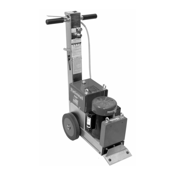
5280 GENERAL OPERATION SPECIFICATIONS SPECIFICATIONS #5280 Length: 25.5'' Width: 11.5'' Height: 38.5'' Weight (machine only): 207 lbs. Speed: 12 - 50 feet per minute MOTOR INFORMATION RPM: 1725 Volts: Amps-Full Load: Under 10 Continuous Duty A well -maintained machine is a productive machine. If not properly maintained, it could be unsafe and could break down. -
Page 11: Maintenance
5280 GENERAL OPERATION MAINTENANCE 1. Always wear eye protection. 2. Keep flammable and fragile objects away from this tool. 3. Always check nuts and bolts to make sure they are tight. 4. Always use the tool with proper voltage specified in the machine’s name plate. 5. -
Page 12: Transportation
5280 TRANSPORTATION WARNING: When maneuvering machine on any type of a incline (ramp, hill, etc.), wheel engage pins MUST be in place (in engaged mode) (See Figure B) and counterweights removed. LOADING ALWAYS REMOVE ALL COUNTERWEIGHTS AND BLADES BEFORE LOADING OR UNLOADING. LIFTING BAIL •... -
Page 13: Unloading
5280 TRANSPORTATION UNLOADING • Position machine at the back of the truck in line with the ramp (See Figure B). • Carefully move machine onto ramp leaving cutting head down (in contact with ramp surface). WARNING: Ramp must have good contact with the back of the vehicle. Failure to do so could cause ramp to lose contact with back of vehicle resulting in damage to the machine or injury to the operator. -
Page 14: Blades
5280 BLADES BLADE SETTING • Dull blades greatly reduce cutting ability. Re-sharpen or replace as needed. • Proper blade size and placement, depending on material and sub-floor type, affects performance. • The harder a job comes up, for best results, use a smaller blade. •... -
Page 15: Blade Changing
5280 BLADES BLADE SETTING (continued) • Self scoring blades are available in a number of sizes. These blades eliminate the need for pre-scoring material. Depending upon the type of material being removed and the sharpness of the blade and scoring wings, the self scoring blades may make it harder to control the machine. •... -
Page 16: Blade Sharpening
5280 BLADES BLADE SHARPENING • Always wear gloves and safety glasses. • Using hand grinder, block up front of machine so blade is off the floor. • Grind blade using a 4" diameter disk with 120 or finer grit. Be careful not to catch disk on edge or corner of blade. -
Page 17: Blades
5280 BLADES Double Edge Sharp Blade Support .062 Sharp .062 .094 Heavy Duty .062 .250 Standard Extra Heavy Duty Self-Scoring Corner Swivel Head .187 Attachment .062 SELF SCORING BLADES: Eliminates pre-scoring carpet. See sizes and accessories on Page 17.1. #6253 RIPPER TEETH: Used on real hard to remove goods;... -
Page 18: Blade Chart
5280 BLADES Part # Description Application Thickness #130-S 3'' x 10'' Blade with slots Glued down carpet, tile or resilient .062 #130-D 3'' x 10'' Blade with both edges sharpened Carpet, tile or resilient on wood & concrete floors .062 #131-S 3'' x 16'' Blade with slots Glued down rubber carpet, floor accumulation... -
Page 19: Procedures
5280 PROCEDURES WHEEL REMOVAL • Examine back of wheels (with a flashlight is helpful) to see if debris is built up. • Keep clean from yarn build up. • Unplug machine. • Lay machine on its side. Wheel • Use provided 3/16" allen wrench. Securing •... -
Page 20: Speed Control & Speed Control Replacement
5280 PROCEDURES SPEED CONTROL • Speed control knob can be adjusted while machine is running. • Turning speed control knob counter clockwise will make machine run faster (See Figure C). • Turning speed control knob clockwise will make machine run slower (See Figure C). SPEED CONTROL REPLACEMENT •... -
Page 21: Checking & Changing Hydraulic Fluid
5280 PROCEDURES HYDRAULIC FLUID LEVEL • Machine is run at a low temperature and pressure. • Check fluid level if there has been a leak, damaged or ruptured hose or a loose fitting. • Fluid level should be 1'' from the top of the tank (See Figure B). ADDING OR CHANGING HYDRAULIC FLUID •... -
Page 22: Troubleshooting
5280 TROUBLESHOOTING IF THERE IS NO FORWARD OR REVERSE: 1. Check speed control valve. Turn counterclockwise to open valve. 2. Check belt. Remove front cover plate (#6280-145) and inspect. IF MOTOR SHUTS OFF OR WILL NOT START: 1. Push reset button located on electric box on motor, located on right hand side (See Figure A). See label on motor. - Page 23 5280 WIRING DIAGRAM ON/OFF SWITCH WIRE DIAGRAM • 2 blue wires to right spades • 2 white wires to left spades • Power source wires always go to copper spades Page 22...
- Page 24 120 VOLT WIRING DIAGRAM Page 23...
- Page 25 5280 HYDRAULIC LINE LAYOUT Page 24...
- Page 26 5280 COMPLETE PARTS LIST PART # DESCRIPTION 5280-1 DRIVE CHAIN 40 STRAND 5280-1L MASTER LINK 5280-2 AXLE SPROCKET 40 BS 13 X 3/4'' 5280-3 HYDRAULIC MOTOR SPROCKET 40 BS 12 X 1 5280-4 PUMP DRIVE BELT 5280-8 CUTTING HEAD 5280-9 WHEEL SPACER (NOT SHOWN) 5280-12 AXLE CLIP 1000-087 ST (4)
- Page 27 5280 COMPLETE PARTS LIST PARTS (continued) PART # DESCRIPTION 6280-161D FILLER CAP (NEW STYLE) 6280-162G MAGNET 6280-112 WHEEL CAP 6280-170A HANDLE BAR GRIP (2) 6280-180 MOTOR LINE (2) 6280-181 PRESSURE LINE 6280-182 RETURN LINE 6280-207 ON/OFF SWITCH 6280-209 PRESSURE CARTRIDGE VALVE 6280-215 VALVE BLOCK ASSEMBLY 6280-404...
- Page 28 5280 COMPLETE PARTS LIST ACCESSORIES PART # DESCRIPTION 5280-401 ADDITIONAL FRONT WEIGHT 5280-402 OPTIONAL SADDLE WEIGHT 5280-500 SWIVEL HEAD ATTACHMENT 6254 50' POWER CORD 73216 3/8-16 X 1-3/4 HEXHEAD BOLT (FOR 1 ADD. WEIGHT) (NOT SHOWN) 73220 3/8-16 X 3 HEXHEAD BOLT (FOR 2 ADD. WEIGHTS) (NOT SHOWN) BLADES PART # DESCRIPTION...
- Page 29 5280 COMPLETE PARTS LIST LABELS PART # DESCRIPTION CAUTION SHARP BLADES LABEL (2) CAUTION CORD LABEL L95B ON/OFF SWITCH LABEL L95C FORWARD LABEL L95E SPEED CONTROL LABEL L95F FLUID LEAK LABEL L95G FLUID LEVEL LABEL (NOT SHOWN) L95J 110V LABEL (NOT SHOWN) L141 FLAG LABEL (2) L173A...
- Page 30 5280 PART NUMBERS & DIAGRAMS 73231 74650 73205 73204 74650 74650 74650 74654 62182 132C -151 132D 72353 4 BHCS 74649 62190 62191 62192 2 BOLTS 74650 71092 73903 103B 71092 71131 PART # DESCRIPTION PART # DESCRIPTION 5280-221 Hydraulic Motor Connector (2) 5280-1 Drive Chain 40 Strand 62182...
- Page 31 5280 PART NUMBERS & DIAGRAMS 167B 6280-170A 74630 167C 74619 74619 74630 6280-207 6280-170A 73002 208A 73032 172A 73005 PART # DESCRIPTION PART # DESCRIPTION 5280-117 Pressure Hose to Pump Connector (3) 6280-170A Handle Bar Grip (2) 6280-180 Motor Line (2) 5280-167 Handle Body 6280-181...
- Page 32 5280 PART NUMBERS & DIAGRAMS 6280-207 6280-208A 74402 5280-404 74623 137W 5280-161C 6280-161D 73228 73228 62180 62190 62182 62192 73255 73315 73902 72353 74649 74623 PART # DESCRIPTION PART # DESCRIPTION 5280-111 Drive Wheel 6280-404 Blade Wrench Holder 5280-136 Blade Cover 62180 Motor Fan Cover 5280-137W Blade Wrench...
- Page 33 5280 PART NUMBERS & DIAGRAMS 172A 73502 74650 74650 74645 139C PART # DESCRIPTION PART # DESCRIPTION 5280-139C Handle Vibration Isolator (2) 73502 1/2 Straight Strain Relief (2) 5280-168 Power Cord 74645 M10-16 Wizlock Bolt (4) 5280-172A Handle Lever 74650 M10-25 Wizlock Bolt (10) 5280-178 Power Cord Strain Relief...
- Page 34 5280 PART NUMBERS & DIAGRAMS 5280-161C 6280-161D 70601 62504 72816 162E PART # DESCRIPTION PART # DESCRIPTION 5280-120 Suction Line 6280-162G Magnet (Not Shown) 5280-161C Hydraulic Tank Filler Cap (Old Style) 62504 Cap O-Ring (for Old Style Plug) 5280-162 Hydraulic Tank Body 70601 Tank Mounted Strainer 5280-162E...
- Page 35 5280 PART NUMBERS & DIAGRAMS 73217 73217 73211 73211 73217 73217 73211 73211 PART # DESCRIPTION PART # DESCRIPTION 5280-8 Cutting Head 73211 3/8-16 Wizlock Nut (4) 73217 3/8-16 x 3/4 Lowhead Socket Bolt (4) 5280-133 Cutting Head Support (4) Page 34...
- Page 36 5280 LABELS L95C L95B L95E L188 L189 L220 L175 L173A L141 L95F PART # DESCRIPTION PART # DESCRIPTION Caution Sharp Blades Label (2) L141 Flag Label Caution Cord Label L173A 5280 Label L95B On/Off Switch Label L175 National Label,Small L95C Forward Label L188 Caution General Info Label...
- Page 37 5280 ACCESSORIES #5280-402 REPLACEMENT SADDLE WEIGHT Adds an extra 45 lbs. to the drive wheels. #5280-500 SWIVEL HEAD ATTACHMENT Unique Swivel Head rotates to use the second sharp edge of the blade without having to remove the blade. Designed to hold razor/scraper blades.
- Page 38 5280 MATERIAL SAFETY DATA Page 37...
- Page 39 5280 MATERIAL SAFETY DATA Page 38...
- Page 40 5280 MATERIAL SAFETY DATA Page 39...
- Page 41 5280 MATERIAL SAFETY DATA Page 40...
- Page 42 5280 MATERIAL SAFETY DATA Page 41...
- Page 43 5280 MATERIAL SAFETY DATA Page 42...
- Page 44 A freight damage claim must be filed with the carrier by the purchaser, the shipper cannot file the freight claim. To obtain service contact National Flooring Equipment, Inc. toll free at 800-245-0267 for a repair authorization number. COD freight returns will not be accepted. Freight collect shipments will not be accepted.
- Page 45 5280 RETURN SHEET Company Name Contact Name Telephone Number Approximate Usage (hours) Problems Encountered Check One: Repair Do you wish to be contacted before repairing Return Contact National if a loaner is needed Return Authorization Number Date required, contact National Customer Number if known Purchased From...
- Page 46 .062 All orders and payment terms to be verified prior to shipping. National Flooring Equipment, Inc. • 9250 Xylon Avenue • Minneapolis, MN 55445 U.S.A. Phone 800-245-0267 or 763-535-8206 • Fax 800-648-7124 or 763-535-8255 Web Site: www.nationalequipment.com • E-Mail: info@nationalequipment.com...
Need help?
Do you have a question about the PANTHER 5280 and is the answer not in the manual?
Questions and answers