
Related Manuals for National Flooring Equipment 5625


Summary of Contents for National Flooring Equipment 5625
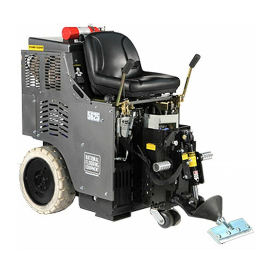
- Page 1 5625 PROPANE RIDE-ON SCRAPER SERVICE MANUAL Read Manual Before Servicing Machine 402962 Rev H...
-
Page 3: Table Of Contents
Table of Contents Table of Contents ................................3 Specifications ................................4 Safety ..................................... 5 General Rules for Safe Operation ......................... 5 Ride-On Scraper Safety Guidelines ........................6 Hydraulic Safety ..............................7 Maintenance Schedule ..............................8 Troubleshooting Guide ..............................9 Maintenance ................................. 10 Remove Slide Plate ............................ -
Page 4: Specifications
Dual Lift Dual Lift Manual Lift 7050-P Propane Tank Top Bracket Propane Tank ATTENTION: NATIONAL FLOORING EQUIPMENT (NFE) DOES NOT SUPPORT CONVERTING THE 7050-P PROPANE TANK TO A TOP BRACKET CONFIGURATION. THIS CONFIGURATION IS NOT AVAILABLE UNLESS APPROVED BY NFE. -
Page 5: Safety
Read the manual carefully to learn equipment applications and limitations, as well as potential hazards associated with this type of equipment. Keep manual near machine at all times. If your manual is lost or damaged, contact National Flooring Equipment (NFE) for a replacement. Personal Equipment Dress properly and use safety gear. -
Page 6: Ride-On Scraper Safety Guidelines
Safety Safety RIDE-ON SCRAPER SAFETY GUIDELINES Before use, anyone operating this equipment must read and understand these safety instructions. Battery Scraping Do not drive machine along hills or uneven surfaces. Remove personal metal items when working with batteries. The weight of the machine may become distributed differently if on A battery can produce a short circuit current sufficient enough to an uneven surface. -
Page 7: Hydraulic Safety
Safety HYDRAULIC SAFETY Maintaining a Safe Work Environment Establishing a safe work environment in and around your hydraulic equipment is extremely important. The easiest and most effective way to avoid problems is to make sure associates understand their equipment, know how to operate the machines safely, and recognize the dangers if handled carelessly. -
Page 8: Maintenance Schedule
Maintenance Schedule Interval After After initial initial First 8 1000 Maintenance to be performed Daily 50 hrs Check all machine components for build ● up; clean if necessary Inspect all safety devices (e-stop, backup ● beeper, seat switch) Inspects for leaks (hoses and fittings) ●... -
Page 9: Troubleshooting Guide
Troubleshooting Guide Problem Cause Solution Scraper does not work when pump is gener- Severe blockage in wheel drive motor hoses. Check hoses for blockage and replace hose ating pressure. if necessary. Wheel drive motors defective. Call NFE service center. Hoses are worn. Hoses rubbing on components. -
Page 10: Maintenance
Maintenance REMOVE SLIDE PLATE Follow shut-down procedure. Remove slide plate pin. Remove cutting head bolt. Remove cylinder from slide plate. Remove slide plate (Figure 1). Follow shut-down procedure. Unplug hydraulic lines from cylinder. A small amount of oil may leak out of the lines. Cap lines or bleed them into a container;... -
Page 11: Check Engine Oil
Maintenance Change Cylinder Check Oil Here Follow shut-down procedure. Disconnect cylinder lines. Have a container ready to catch oil from lines. Add Oil Here Remove cylinder securing hexhead bolt from lower cutting head support. Remove clips and pin from cylinder and slide plate. Remove cylinder upper pin. -
Page 12: Change Valve
Maintenance CHANGE VALVE Follow shut-down procedure. Lift hood and secure in place. Loosen hoses; unbolt valve so that it hangs down. Mark hoses to ensure proper orientation during re-attachment. Re-mount new valve. Transfer hoses to the new valve one at a time, ensuring correct placement. FIG. -
Page 13: Additional Engine Maintenance
Maintenance ADDITIONAL ENGINE MAINTENANCE See enclosed Kawasaki Manual. CAUTION: THE BACKUP BEEPER IS ON THE MACHINE FOR SAFETY. IT IS IMPORTANT TO KEEP IT IN GOOD WORKING CONDI- TION. FAILURE TO DO SO COULD CAUSE BODILY INJURY. CASTER ASSEMBLY Keep clean and free of debris; make sure it can move freely. Give a shot of grease in grease zerk on caster as needed to keep moving freely. -
Page 14: Parts List And Diagrams
Parts List and Diagrams EXTERNAL PARTS USAGE: S/N: 5625-12XXXX S/N: 5625-23XXXX S/N: 5625DL-23XXXX WEIGHT PARTS 11 17 WEIGHT PARTS 22 23 ENGINE PARTS HYDRAULIC PARTS ITEM PART DESCRIPTION QTY. NUMBER 400321 Armrests, Kit for Plastic Seat 401999 Knob, Adjustable, 3/4"... -
Page 15: Motor Pod Assembly
Parts List and Diagrams MOTOR POD ASSEMBLY EXHAUST DETAIL PUMP/DRIVE DETAIL 42 15 13 ITEM ITEM PART NUMBER DESCRIPTION QTY. PART NUMBER DESCRIPTION QTY. 400191-1 Cover, Battery, Top 404138 Cable, Battery, Black, 24" 400280 Barrier, Heat, Adhesive Back 404143 Assembly, Cable, Throttle, Motor Pod 401418 Rod, Threaded, 5/16-18x9 5200-116... -
Page 16: Pump Drive Assembly
Parts List and Diagrams PUMP DRIVE ASSEMBLY ITEM PART NUMBER DESCRIPTION 70905-D7 Pump, Double, Marzocchi 5200-1G Gasket, Pump 73204 Washer, Lock, 3/8 401414 Cover, Bell Housing 70951 Coupler, Lovejoy, Splined 70953 Spider 70954 Coupler, 1-1/8" 404156 Screw, Ferry Cap, 3/8-16 x 1, 12pt, Black Oxide 400179 Housing, Bell Pump, Machined 73001... -
Page 17: Hood Support
Parts List and Diagrams HOOD SUPPORT ITEM PART NUMBER DESCRIPTION QTY. 73238 Bolt, Flange 3/8-16x1-1/2 401963 Spacer, Hood Strap, Body 400172 Support, Hood 400189 Nut, Acorn, Nickel Plated, 3/8-16 401452 Washer, Flat, 1/2", SAE 402116 Spacer, Hood Strap, Hood 73231 Bolt, Button Head, Flange, 3/8-16 73207 Nut, NyLock 3/8-16... -
Page 18: Dual Lift
Parts List and Diagrams DUAL LIFT ITEM *-NOT SHOWN PART NUMBER DESCRIPTION QTY. Housing, Hydraulic 402423 Adjustment, Wldt Slide Plate, Hydraulic 402432 Adjustment, Wldt Pin, Lower Cutting Head 401429 Support SSS, 3/8-24 x .25, Black 401876 Oxide 402440 Tooling Holder, Weldment 5110-250 Cylinder NN16 6500-31... -
Page 19: Manual Lift
73531 Washer, Flat Zinc, SAE 5/8 73424 Washer, Flat, Zinc SAE 1/2 73414 Bolt, HHCS, 1/2-13x7 73427 Bolt, Hex Head Cap 1/2-13x1-1/2 BRACKET ASSEMBLY (5625-13XXXX ONLY) ITEM NO. PART NUMBER DESCRIPTION QTY. Bracket, Tank, 33 Pound, LP, 402136 402105 Bracket, Light, AUS... -
Page 20: Beacon Assembly
Parts List and Diagrams BEACON ASSEMBLY (5625-13XXXX ONLY) ITEM NO. PART NUMBER DESCRIPTION QTY. 70629 Light, Flashing 72790 Connector, Male, 2 Pole Wire, Primary, 14 GPT-500- 72568 RED (TSC) Wire, Primary, 14 GPT-500- 72569 BLK (TSC) 72770 Terminal, 14-12 Gauge, Male... -
Page 21: Levers (Manual Lift)
Parts List and Diagrams LEVERS (MANUAL LIFT) ITEM ITEM PART NUMBER DESCRIPTION QTY. PART NUMBER DESCRIPTION QTY. 400034 Fitting, FF1231-06-08 402416 Assembly, Valve Handle, Right 73320 Bolt, Socket Head Cap 5/16-18x2 401797 Bracket, Universal, Lever 73211 Nut, Flange, Serrated, 3/8-16 401408 Spacer, Round, .323 X .625 X .675 5700-60... -
Page 22: Levers (Dual Lift)
Parts List and Diagrams LEVERS (DUAL LIFT) ITEM ITEM PART NUMBER DESCRIPTION QTY. PART NUMBER DESCRIPTION QTY. 400034 Fitting, FF1231-06-08 402416 Assembly, Valve Handle, Right 73320 Bolt, Socket Head Cap 5/16-18x2 401797 Bracket, Universal, Lever 401408 Spacer, Round, .323 X .625 X .675 400137 Fitting, 1/2 - 1/4, JIC 5700-60... -
Page 23: Hydraulics
Parts List and Diagrams HYDRAULICS ITEM PART NUMBER DESCRIPTION QTY. 401574 Plate, Suction 5110-114-2 Fitting, Wheel Motor 5110-234-1 Pipe, Relief Valve 5110-234 Coupler, Relief Valve 5200-261 Hose, Hydraulic, 3/8 x 40, F/45F 5700-67 Plug, Tank 5700-77 Hose, Hydraulic, 1/2 x 13.5, M/F 5700-93 Gasket 70655... -
Page 24: Headlight Assembly
Parts List and Diagrams HEADLIGHT ASSEMBLY ITEM PART NUMBER DESCRIPTION 403976 Switch, Rocker, SP, 14V, 16 A 404009 Shroud, Worklight, Rider, Low Profile 404041 Light, Work, 6"x2", Flush, 18W 404060 Screw, Button Head Cap, M5x0.8x10, Black Oxide 74631 Bolt, Wizlock, M6-16 24 24... -
Page 25: Labels
NATIONAL LABEL, 5.5 X 6 19 L318* DO NOT TOUCH LABEL 9 L223* LABEL, PATENT 20 L319* BURN HAZARD LABEL 10 402012 LABEL, 5625 LOGO 21 402149 FORKLIFT POINT LABEL 11 L314 LP GAS LABEL 22 402376 RIDE-ON LIFT LABEL * NOT SHOWN... -
Page 26: Wiring
Parts List and Diagrams 5625 MAIN WIRING DIAGRAM 12V BATTERY STARTER CHASSIS 4-BLK 4-BLK ENGAGE 14-RED 20A FUSE 16-BLK 16-BLK FHSP2 16-YEL IGNITION ENGINE SWITCH HARNESS 14-RED 14-RED FHSP1 14-RED POWER CHARGING COIL 14-BLK 16-WHT 16-WHT IGNITION IGNITION COIL 14-RED/YEL... - Page 27 Parts List and Diagrams 5625/8000 SEAT WIRING DIAGRAM TO MAIN WIRING T-F4 16-WHT SEAT SP20 T-F3 16-BLK SWITCH LIGHT SWITCH 18-RED T-F3 T-F2 18-ORG SP30 WORK LIGHT T-M1 T-F1 18-BLK 18-BLK 16-BLK 18-BLK BEACON 16-RED 18-ORG...
-
Page 28: Warranty
Warranty National Flooring Equipment Inc. (referred to as “The Company”) warrants that each new unit manufactured by The Company to be free from defects in materials and workmanship in normal use and service for a period of twelve (12) months from date of shipment from The Company to the end user. - Page 32 NATIONAL FLOORING EQUIPMENT 9250 Xylon Avenue N • Minneapolis, MN 55445 • U.S.A. Toll-free 800-245-0267 • Phone 763-315-5300 • Fax 800-648-7124 • Fax 763-535-8255 Web Site: www.nationalequipment.com • E-Mail: info@nationalequipment.com...
Need help?
Do you have a question about the 5625 and is the answer not in the manual?
Questions and answers