
Related Manuals for National Flooring Equipment 8000


Summary of Contents for National Flooring Equipment 8000
- Page 1 RevA PROPANE POWERED RIDE-ON MACHINE Caution: Read Manual Before Operating Machine...
-
Page 3: Table Of Contents
Table of Contents Table of Contents ........................................ 3-4 Features and Specifi catons ....................................5 Safety ............................................ 6-9 General Rules for Safe Operation ................................6-7 Characteristics of a Defensive Operator ............................... 7 Hydraulic Safety Tips ....................................7 Safety Switch ........................................ 8 Safety Precautions...................................... -
Page 4: Table Of Contents
Table of Contents Handle Parts ....................................... 41 Valve Assembly ......................................42 Suction Assembly ....................................... 43 Seat Adjuster ......................................44 Seat Switch ......................................... 44 Rear Frame Cover ...................................... 44 Hood Bumper Assembly ..................................... 44 Hood Support Parts ....................................45 Dipstick Parts ......................................45 Weights ........................................ -
Page 5: Features And Specifi Catons
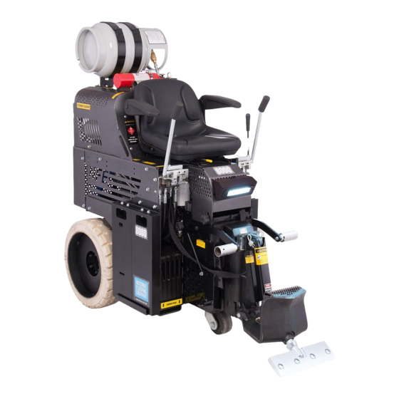
Features and Specifi cations Fire Extinguisher Propane Fuel Tank Cylinder Adjustment Hydraulic Steering Adjustable Foot Pegs Adjustable Slide Plate Non-Marking Tires Fork Lift Cups Quick-Change Swivel Cutting Head FEATURES Non-marking Tires - Large non-marking tires, work on all types of Quick-Change Swivel Head - Assures continuous blade contact with application and debris build up. -
Page 6: Safety
Safety GENERAL RULES FOR SAFE OPERATION READ AND SAVE ALL INSTRUCTIONS FOR FUTURE USE. Before use, ensure operators reads and understand this manual. Read and understand labeling on machine and components. All operators must view the instruction video. Extra copies of the manual and video are avail- able. -
Page 7: Characteristics Of A Defensive Operator
Safety 25. DO NOT ALLOW the cutting heads to come into contact with the supply cord. 26. REGULARLY EXAMINE the supply cord for damage, such as cracking or aging. If damaged, replace the cord before further use. Only replace the supply cord with the type specifi ed in this manual. CHARACTERISTICS OF A DEFENSIVE OPERATOR A Good Operator is a “Defensive”... -
Page 8: Safety Switch
USE CARBON MONOXIDE DETECTOR WHEN OPERATING MACHINE Included with the 8000 are a 75007 lapel CO Monitor and a 75008 Clip. it is recommended that the operator and anyone in the working vicinity wear the detector. Failure to do so could cause bodily injury and/or death. The use of detectors helps to verify if work area is safe from Carbon Monoxide poisoning. -
Page 9: Safety Precautions
GASES, DUST, STEAM, SMOKE Do not weld, fl ame cut or perform grinding work on the 8000 Propane Ride-On without written authorization from the manufacturer. The danger of fi re or explosion exists when work of this nature is done. Begin maintenance work only when the machine is in Shut Down Mode (turned off). -
Page 10: Machine Operation
Machine Operation MACHINE START-UP PROCEDURE Key Start POWER/Key Start (Figure A) Open propane tank valve by turning knob CCW until fully open. Green Light Operator must be seated in seat. The machine will not start unless the operator is seated. Red Light Insure that hydraulic levers are “centered”. -
Page 11: Seat Switch
(Figure E). Never use the cutting head only. SHUT DOWN MODE (SHUT DOWN PROCEDURE/ TURNED OFF) Move the 8000 to level ground. Turn off the ignition switch and remove the key. FIG. E DO NOT move hydraulic levers. -
Page 12: Changing Propane Tank
Disconnect Here Included with the 8000 are a 75007 Lapel CO Monitor and a 75008 Clip. It is recom- mended that the operator and anyone in the working vicinity wear the detector. Failure to do so could cause bodily injury and/or death. The use of detectors helps to verify if work area is safe from Carbon Monoxide poisoning. -
Page 13: Loading/Unloading
Machine Operation LOADING/UNLOADING • Always remove blade and cutting head when machine is being moved or trans- ported • Cutting head and slide plate can be removed to make the machine more compact. • NEVER leave machine unattended on an incline. •... -
Page 14: Center Of Gravity
Machine Operation WHEEL CHOCKS Wheel chocks will help to secure the machine but DO NOT use wheel chocks alone to secure the machine. CENTER OF GRAVITY Be aware of your surroundings and machines operating angles. When changing from a low slide plate to a high slide plate setting or a low cutting head angle to a high cutting head angle, the operating “attitude”... -
Page 15: Wheel Size
Machine Operation TO MOVE MACHINE WITHOUT POWER (PUSHING MACHINE) Forward: To move the machine forward, levers need to be pushed forward. To lock levers in place, connect a bungee-strap from each lever (pushing levers forward), pulling straps down to and connecting to the front plate (See Figure T). Never leave machine unattended with strap holding levers open. - Page 16 Machine Operation SHEAR POINT The shear point is the point where material to be removed will cut cleanly from the fl oor. If the blade is too wide, too dull, or too steep, the shear point is lost. WEIGHT VS. SHARPNESS The most common way to compensate for a dull blade is to add more weight and raise the blade angle (see re-scrape set up Page 19).
-
Page 17: Blade Setting
Machine Operation ADJUSTING THE DUAL LIFT HYDRAULIC SLIDE PLATE (CONT.) A “high” setting has the hydraulic slide plate positioned six inches off the fl oor or in most cases fl ush with the bottom of the slide plate channel guide. This setting is most often used for re-scraping glues, mastics, thin sets and soft coatings. - Page 18 Machine Operation • Dull blades greatly affect the performance of the machine and reduce cutting ability, Blade Securing Bolt Cutting Head resharpen or replace as needed. • Keep your work area clean and clear of debris. • After you have removed a portion of material, remove it out of the way. This will give the machine maximum performance and help to keep the work area safe.
- Page 19 Machine Operation DOUBLE STICK CARPET SET-UP Slide plate should be set low, slide plate should be set to the lowest setting or approximately 2.5 cm (1”) off the fl oor. It is best to test to see which is the easiest way to remove double stick. Start with a Cutting Head from 25.4 to 35.5 cm (10” to 14”) with Self-Scoring Blades. If self- scoring blades do not work, score thru the carpet the width of the blade (Standard Blade) and scrape up.
-
Page 20: Ditching
Machine Operation DITCHING CROSS ROOM DITCHING When removing hard to remove ceramic, VCT or VAT, cross-room ditching will help to make the removal easier. Using a blade 5 to 15.25 cm (2” to 6”) in width, make ditches 30 to 60 cm (1’ to 2’) apart in the same direction the machine will be removing the goods (See Figure BB). This “relieves”... -
Page 21: Blades
Blades STANDARD BLADE (FIGURE FF) This heavy duty blade is designed to remove soft goods, carpet, and vinyl fl ooring. Its .062 thickness offers fl exibility to maximize the shear point angle. PART# DESCRIPTION THICKNESS (IN.) 5” X 16” BLADE .062 4”... - Page 22 Blades PREMIUM HIGH TEMPERED BLADES (FIGURE KK) These ultra-high quality spring steel blades are extra hard; ensuring long blade life between sharpenings. They work on all glued down carpets, VCT, VAT, rubber tile, cork, re-scraping adhesive and elastomeric coatings. Great for fl oor accumulations! PART# DESCRIPTION THICKNESS (IN.)
- Page 23 Blades TAPERED CUTTING HEAD SHANKS (FIGURE PP) The longer taper works great on tough wood fl oors (glued & nailed). The long length allows the blade to easily slide under tough materials. They work through most ceramics and VCT. PART# DESCRIPTION THICKNESS (IN.) 7076-8...
-
Page 24: Machine Maintenance
Machine Maintenance CAUTION: LET ENGINE COOL BEFORE ANY MAINTENANCE. FAILURE TO DO Breather SO COULD CAUSE SERIOUS BODILY INJURY. Dip Stick DUAL SLIDE PLATE REMOVAL Lower the slide plate to the fl oor and place a block under the assembly. Remove the front cylinder by taking the 1/2”... -
Page 25: Hydraulic Cylinder Change Out
Machine Maintenance REPLACE IN-TANK STRAINERS Remove the (8) socket head cap screws that hold down the top suction assembly. Carefully pull the suction assembly out as far as you can. Reach in to the reservoir and unscrew the strainers from the end of the suction hose. Screw in the replacement strainers to the end of the suction hose. -
Page 26: Pump Change Out
Machine Maintenance PUMP CHANGE OUT Lift and secure hood. Disconnect hydraulic lines. Remove two 3/8”-16x1 pump bolts. Remove pump by pulling pump straight out from pump motor. VALVE CHANGE OUT Disconnect machine from power (charger or battery). FIG. UU Lift hood and secure in place. Remove hoses from valve body. -
Page 27: Seat Replacement
Machine Maintenance CHANGING HYDRAULIC FLUID FILTER Remove old fi lter by turning counter-clockwise. Have rag ready to catch excess fl uid that may spill. Install new fi lter on by turning clockwise. SWITCHES There are two switches: • On (Key) Switch FIG. - Page 28 Machine Maintenance CLEAN AIR CLEANER FOAM ELEMENT Wash the element in detergent and water and dry thoroughly. Soak the element in new engine oil and squeeze it to remove excess oil. CLEAN AIR CLEANER PAPER ELEMENT Clean the paper element by tapping it gently against a fl at surface to remove the dust. If the element is very dirty replace it with a new one. You can rinse the element with water and let the element air dry thoroughly before re-installing.
- Page 29 Machine Maintenance Coat a fi lm of clean engine oil on seal of new fi lter. Install new fi lter rotating clockwise until the seal contacts the mountin surface. Rotate fi lter 3/4 of a turn more by hand to fully tighten down. Replace engine oil.
- Page 30 Maintenance Schedule Interval After initial After initial Maintenance to be performed Daily 160 hrs 1000 hrs 2000 hrs 50 hrs 500 hrs Check wheels, caster and wheel motors for build up; and clean ● Check hydraulic oil level ● Inspect all safety devices (e-stop, backup beeper, seat switch) ●...
-
Page 31: Troubleshooting Guide
Troubleshooting Guide Problem Cause Solution 1. The scraper does not work when the pump a. Severe blockage in wheel drive motor a. Check hoses for blockage and replace is generating pressure. hoses hose if necessary b. Wheel drive motors defective b. - Page 32 Troubleshooting Guide Problem Cause Solution 10. Engine dies or cuts out. a. Fuel tank is empty a. Change or fi ll fuel tank b. Oil is low b. Fill oil to proper level c. Operator not seated properly c. Position on seat correctly 11.
-
Page 33: Complete Parts List
Complete Parts List PART# DESCRIPTION PART# DESCRIPTION 1 70353 RETURN LINE 50 400130 KAWASAKI MOTOR 2 70602 INSTRUCTION MANUAL TUBE 51 400131 BOLT HEX HEAD 5/8-11X7 3 70603 INSTRUCTION TUBE CAP 52 400132 HEX HEAD CAP SCREW 1/2-13X4 YELLOW 4 70627 BRACKET, TANK, 33 POUND, LP ZINC GRADE 8 5 70651... - Page 34 Complete Parts List PART# DESCRIPTION PART# DESCRIPTION 101 5200-603 GUIDE HOSE (NOT SHOWN) 129 L137 DISARM MACHINE LABEL 102 5200QL-14 BACKUP BEEPER PIN ASSEMBLY 130 L141 FLAG/MADE IN USA LABEL 103 5200QL-27 MAIN BASE (NOT SHOWN) 131 L142 TRAILER HITCH LABEL 104 5200QL-34 REVERSE CATCH (NOT SHOWN) 132 L165...
-
Page 35: Parts List And Diagrams
Parts List and Diagrams EXTERNAL PARTS PART# DESCRIPTION PART# DESCRIPTION 1 5110-111 SEAT, RIDE-ON 8 70627 BRACKET, HORIZONTAL TANK 2 70602 TUBE, INSTRUCTION MANUAL 9 401798 HANDLE WLDT, LH, VALVE 3 401697 WHEEL 21” 10 401799 HANDLE WLDT, RH, VALVE 4 401560-SV PANEL, SIDE, RIGHT, SILVER VEIN 11 75006... -
Page 36: External Parts
Parts List and Diagrams EXTERNAL PARTS (CONT’D) PART# DESCRIPTION PART# DESCRIPTION 1 401669 COVER, UPPER HOSE 4 5200-603 HOSE GUIDE 2 401597 DOUBLE WHEEL CASTER ASSEMBLY 5 5110-180 FOOT PEG 3 74854 WEIGHT, POCKET, CAST, RIDE-ON 6 400164 KNOB, THREE-LOBE 1/2-13 www.nationalequipment.com Phone: 763-315-5300... - Page 37 Parts List and Diagrams SIDE WEIGHT PARTS 7, 8, 9 PART# DESCRIPTION PART# DESCRIPTION 1 401960 WEIGHT, SIDE, HANGING 6 73208 BOLT, HEX HEAD CAP 3/8-16X1-1/2 2 401961 BRACKET, WEIGHT, RIGHT 7 401995 BOLT, WIZLOCK, 3/8-16 X 2.5 3 401962 BRACKET, WEIGHT, LEFT 8 73203 WASHER, FLAT, 3/8...
-
Page 38: Dual Slide Plate
Parts List and Diagrams DUAL SLIDE PLATE PART# DESCRIPTION PART# DESCRIPTION 1 401568 SUPPORT, TOOLING CARRIER, CAST 7 5110-250 CYLINDER NN16 2 401566 DUAL LIFT, FRAME, CAST 8 6500-30 PIN, LOWER BACK 3 6500-11 SLIDE PLATE, DUAL LIFT, CAST 9 72801 FITTING, 90 DEGREE, 1/4”... -
Page 39: Front Cylinder Assembly
Parts List and Diagrams PART# DESCRIPTION FRONT CYLINDER ASSEMBLY 1 5110-250 CYLINDER NN16 2 5110-251 ROD, CYLINDER CONNECT 3 72801 FITTING, 90 DEGREE, 1/4” 4 400132 BOLT, HEX HEAD, 1/2 13 X 4 5 73402 NUT, NYLOCK 1/2 13 6 73536 PIN, HITCH CLIP 5/8”... -
Page 40: Wheel Motor
Parts List and Diagrams WHEEL MOTOR PART# DESCRIPTION 1 401592 WHEEL MOTOR, POCLAIN W/BRAKE 2 5110-114-2 FITTING, WHEEL MOTOR 3 5110-264 FITTING, VALVE, 45 DEGREE WHEEL MOTOR HOSES PART# DESCRIPTION 1 401632 HOSE, WHEEL MOTOR, HIGH PSI 2 5200-261 HOSE, WHEEL MOTOR 3 5700-75 HOSE, 12.5’’... -
Page 41: Foot Peg Assembly
Parts List and Diagrams PART# DESCRIPTION FOOT PEG ASSEMBLY 1 5110-180 PEG, FOOT 2 73238 BOLT, FLANGE 3/8 16X1 1/2 3 73207 NUT, NYLOCK 3/8 16 PART# DESCRIPTION INSTRUCTION TUBE PARTS 1 70602 INSTRUCTION MANUAL TUBE 2 70603 INSTRUCTION TUBE CAP 3 74425 10/32 K-LOCK NUT PART#... -
Page 42: Caster Wheel Assembly
Parts List and Diagrams CASTER WHEEL ASSEMBLY PART# DESCRIPTION 1 401597 CASTER, DOUBLE GRAY 2 73406 BOLT, HEX HEAD CAP 1/2 13X1 1/4 3 73424 WASHER, FLAT, ZINC SAE 1/2 (NOT SHOWN) 4 4 73403 WASHER, SPLIT LOCK 1/2 (NOT SHOWN) 4 HEAT DEFLECTOR PART# DESCRIPTION... - Page 43 Parts List and Diagrams PART# DESCRIPTION BACKUP BEEPER 1 5110-218 SWITCH, BACK-UP BEEPER 2 5200QL-14A PIN, BACK-UP BEEPER 3 70712 SPRING, COMPRESSION, 151-A 4 73910 E-CLIP, 3/16 5 74517 SCREW, PHILLIPS PAN HEAD MAC 6-32X1 2 6 74501 WASHER, #6 FLAT SAE (NOT SHOWN) PART# DESCRIPTION BACKUP BEEPER ASSEMBLY...
-
Page 44: Handle Parts
Parts List and Diagrams HANDLE PARTS PART# DESCRIPTION PART# DESCRIPTION 1 400327 HANDGRIP 9 5700-60 BLADE HANDLE 2 401408 HANDLE SPACER 10 73020 WIZLOCK BOLT 1/4-20X5/8 3 401795 BRACKET, VALVE, LH 11 73211 NUT, FLANGE 3/8-16 4 401796 BRACKET, VALVE, RH 12 73227 SET SCREW 3/8-24X1 5 401797... -
Page 45: Valve Assembly
Parts List and Diagrams VALVE ASSEMBLY PART# DESCRIPTION PART# DESCRIPTION 1 6280-221 HYDRAULIC MOTOR CONNECTOR 4 401853 HOSE, PUMP TO VALVE, RH, HIGH PSI 2 400034 FITTING, FF1231-06-08 5 401854 HOSE, PUMP TO VALVE, LH, HIGH PSI 3 401834 HIGH PSI DUAL SPOOL VALVE www.nationalequipment.com Phone: 763-315-5300... -
Page 46: Suction Assembly
Parts List and Diagrams SUCTION ASSEMBLY PART# DESCRIPTION PART# DESCRIPTION 1 401574 PLATE, SUCTION 5 5110-237 FILTER SCREEN 2 5700-77 ASSEMBLY, HOSE 6 400099 HOSE, SUCTION, 1/2” X 20” W/ FITTINGS 2 3 70652 FITTING 7 5700-93 GASKET 4 70655 PIPE, MALE, 10”... -
Page 47: Seat Adjuster
Parts List and Diagrams PART# DESCRIPTION SEAT ADJUSTER 1 401631 SEAT ADJUSTER 2 5200QL-13 SPACER, VALVE LEVER PART# DESCRIPTION SEAT SWITCH 1 5110-207 SWITCH, SEAT PART# DESCRIPTION REAR FRAME COVER 1 401573 REAR FRAME COVER PART# DESCRIPTION HOOD BUMPER ASSEMBLY 1 73020 BOLT, WIZLOCK 1/4-20X5/8 2 5600-66... -
Page 48: Hood Support Parts
Parts List and Diagrams HOOD SUPPORT PART# DESCRIPTION 1 400172 HOOD SUPPORT 2 400178 SHOULDER SHROUD HOLD UP BOLT 3 400189 ACORN NUT 3/8-16 4 401963 HOOD STRAP BODY SPACER DIPSTICK PART# DESCRIPTION 1 5110-234 RELIEF VALVE COUPLER 2 5110-234-1 RELIEF VALVE PIPE 3 80058 BREATHER, WITH 6”... -
Page 49: Weights
Parts List and Diagrams PART# DESCRIPTION WEIGHTS 1 400197 FRONT WEIGHT 2 401484 RIGHT SIDE WEIGHT 3 401485 LEFT SIDE WEIGHT 4 401686 RISER PLATE WEIGHT 5 401960 SIDE WEIGHT HANGING 6 5110-404 REAR WEIGHT PART# DESCRIPTION FILTER 1 70612 BRACKET, FILTER 2 401635 RETURN HOSE... -
Page 50: Drain Plugs
Parts List and Diagrams DRAIN PLUGS PART# DESCRIPTION 1 5110-157 PLUG, DRAIN-FILLER MOTOR POD ASSEMBLY PART# DESCRIPTION 1 6280-118 FITTING, SUCTION HOSE TO PUMP 2 400182S MOTOR POD ASSEMBLY 25HP 3 5200QL-27 BASE, MAIN Fax: 763-535-8255 info@nationalequipment.com... -
Page 51: Labels
9 L231 PATENTS PENDING LABEL 22 402001 NATIONAL LOGO LARGE 10 L314 LP GAS LABEL 23 402059 8000 LABEL 11 L315 CARBON MONOXIDE LABEL 24 L256 AIR FILTER MUST BE KEPT CLEAN LABEL 2 12 L318 DO NOT TOUCH LABEL... - Page 52 Parts List and Diagrams L08-1 L106 DA NGE R CAUTION OPERATOR MUST BE SEATED AND LEVER IN NEUTRAL POSITION BEFORE STARTING UP REVERSE DOWN FORWARD L118 L137 L142 DA N G E R WARNING OPERATOR MUST BE SEATED AND LEVER IN NEUTRAL POSITION BEFORE STARTING Trailer hitch is only intended to move small trailers on the jobsite.
- Page 53 Parts List and Diagrams L33D L561 WARNING! AVSIO ! REMOVE TANK BEFORE Operate by authorized/trained personnel only LIFTING L33D LID! ¡ QUITE EL TANQUE ANTES DE ABRIR EL COFRE! L561 L95F WARNING CAUTION NEVER LOOK FOR A HYDRAULIC FLUID LEAK BY HAND WHILE MACHINE IS UNDER PRESSURE.
-
Page 54: Accessories
Accessories FRONT WHEEL ASSEMBLY 5110-100 Front Wheel Assembly Allows stability and safe transportation over any surface. Easy and quick to attach. CUTTING HEAD EXTENSION 7050-15 Cutting Head Extension Extension for cutting heads to reach under tight areas. PROPANE TANK 7050-P Propane Tank CARBON MONOXIDE MONITOR 75007... -
Page 55: Wiring Diagram
Parts List and Diagrams 8000 WIRING DIAGRAM www.nationalequipment.com Phone: 763-315-5300... -
Page 56: Material Safety Data Sheet Information
Material Safety Data Sheet (MSDS) Information CHEVRON HD 22 - 68 - HYDRAULIC FLUID PRODUCT IDENTIFICATION AND COMPANY IDENTIFICATION Product Number(S): CPS221655, CPS221658, CPS221659 CHEMTREC: (800) 424-9300 or (703) 527-3887 Synonyms: Texaco Rando HD22, Texaco Rando HD 32, Texaco Health Emergency Rando HD 46, Texaco Rando HD 68 Chevron Emergency Information Center: Located in the USA. - Page 57 Material Safety Data Sheet (MSDS) Information CHEVRON HD 22 - 68 - HYDRAULIC FLUID (CONTINUED) EXTINGUSHING MEDIA: Use water fog, foam, dry chemical or carbon dioxide (CO2) to extinguish fl ames. PROTECTION OF FIRE FIGHTERS: Fire Fighting instructions: This material will burn although it is not easily ignited. For fi res involving this material, do not enter any enclosed or confi...
- Page 58 Material Safety Data Sheet (MSDS) Information CHEVRON HD 22 - 68 - HYDRAULIC FLUID (CONTINUED) PHYSICAL AND CHEMICAL PROPERTIES Attention: The data below are typical values and do not constitute a specifi cation. Color: Yellow Physical State: Liquid Odor: Petroleum odor pH: Not applicable Vapor Pressure: <0.01 mmHg @ 37.8 C (100 F) Vapor Density (Air = 1): >1...
- Page 59 Material Safety Data Sheet (MSDS) Information REGULATORY INFORMATION EPCRA 311/312 CATAGORIES: 1. Immediate (Acute) Health Effects: NO 2. Delayed (Chronic) Health Effects: NO 3. Fire Hazard: NO 4. Sudden Release of Pressure Hazard: NO 5. Reactivity Hazzard: NO REGULATORY LISTS SEARCHED: 01-1=IARC Group1 03=EPCRA 313 01-2A=IARC Group 2A...
- Page 60 Fire Extinguisher - MSDS Fax: 763-535-8255 info@nationalequipment.com...
- Page 61 Fire Extinguisher - MSDS (Continued) www.nationalequipment.com Phone: 763-315-5300...
- Page 62 Fire Extinguisher - MSDS (Continued) Fax: 763-535-8255 info@nationalequipment.com...
- Page 63 Fire Extinguisher - MSDS (Continued) www.nationalequipment.com Phone: 763-315-5300...
- Page 64 Fire Extinguisher - MSDS (Continued) Fax: 763-535-8255 info@nationalequipment.com...
- Page 65 Fire Extinguisher - MSDS (Continued) www.nationalequipment.com Phone: 763-315-5300...
- Page 66 Fire Extinguisher - MSDS (Continued) Fax: 763-535-8255 info@nationalequipment.com...
-
Page 67: Guarantee
This warranty gives you specifi c legal rights. You may also have other rights which vary from state to state. WARRANTY PERIOD The 8000 Propane Powered Floor Prep System is guaranteed to be free of manufacturer defective workmanship and in quality of materials for a period of one year. - Page 68 9250 Xylon Avenue N • Minneapolis, MN 55445 • U.S.A. Toll-free 800-245-0267 • Phone 763-315-5300 • Fax 800-648-7124 • Fax 763-535-8255 Web Site: www.nationalequipment.com • E-Mail: info@nationalequipment.com...
Need help?
Do you have a question about the 8000 and is the answer not in the manual?
Questions and answers