
Subscribe to Our Youtube Channel
Related Manuals for National Flooring Equipment 5200QL


Summary of Contents for National Flooring Equipment 5200QL
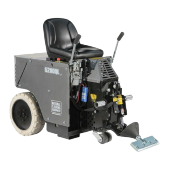
- Page 1 5200QL RIDE-ON SCRAPER SERVICE MANUAL Read Manual Before Servicing Machine 403781 Rev A...
-
Page 3: Table Of Contents
Table of Contents Table of Contents ................................3 Specifications ................................4 Maintenance Schedule ..............................8 Troubleshooting Guide ..............................9 Maintenance ................................ 10 Slide Plate Removal ............................10 Leak Maintenance ............................... 10 Check Oil Level ..............................10 Oil Change Out ..............................10 Change/Remove Hose ............................11 Change Wheel Motor ............................11 Remove/Replace Foot Peg ...........................11... -
Page 4: Specifications
Specifications Product Specifications Width Length Height Weight 24.75” (63 cm) 57” (145 cm) 46.5” (118 cm) 1,315 lbs (597 kg) Fully Weighted Power Speed Input Voltage / Frequency Up to 120 ft/min. 1,760 lbs (798 kg) 4 HP (2.98 kW) 120V / 60 Hz (36.6 m/min.) - Page 5 Read the manual carefully to learn equipment applications and limitations, as well as potential hazards associated with this type of equipment. Keep manual near machine at all times. If your manual is lost or damaged, contact National Flooring Equipment (NFE) for a replacement. Personal Maintenance &...
- Page 6 Safety Scraping Batteries and Chargers Do not drive machine along hills or uneven surfaces. Use caution; risk of explosive gases. The weight of the machine may become distributed differently if on Batteries generate explosive gases during normal operation. Do an uneven surface. Too much of an angle could make the machine not use near fuels, grain, dust, solvents, or other flammables;...
- Page 7 Safety HYDRAULIC SAFETY Maintaining a Safe Work Environment Establishing a safe work environment in and around your hydraulic equipment is extremely important. The easiest and most effective way to avoid problems is to make sure associates understand their equipment, know how to operate the machines safely, and recognize the dangers if handled carelessly.
-
Page 8: Maintenance Schedule
Maintenance Schedule Interval After initial After initial Maintenance to be performed Daily 250 hrs 1000 hrs 2000 hrs 100 hrs 500 hrs Inspect extension cord for damage ● Check wheels, caster and wheel motors for build up; and clean ● Check hydraulic oil level ●... -
Page 9: Troubleshooting Guide
Troubleshooting Guide Problem Cause Solution Machine will not start. Seat safety switch is disengaged. Ensure operator is seated. Emergency stop (E-Stop) switch is disen- Twist E-Stop into the “POWER ON” position. gaged. Circuit breaker is in the OFF position. Verify circuit breaker is in “ON” position. 48 volt blue plugs are not connected. -
Page 10: Maintenance
Maintenance CAUTION: ALWAYS DISCONNECT BATTERY BEFORE MAINTAINING. SLIDE PLATE REMOVAL (FIGURE AB) Disconnect machine from power. Remove slide plate pin, cutting head bolt, cylinder, and slide plate. Disconnect machine from power. Disconnect hydraulic lines from cylinder. A small amount of oil leak out of lines, place rag below line to catch fluid. Cap lines or bleed into a container. -
Page 11: Change/Remove Hose
Maintenance CHANGE/REMOVE HOSE Disconnect machine from power. Remove hood. Using proper wrench size, remove hose from fitting. When replacing, make sure O-ring is properly seated on hose fitting. CHANGE WHEEL MOTOR Disconnect machine from power. Block up machine to remove wheel. Remove wheel. -
Page 12: Change Hydraulic Cylinder
Maintenance CHANGE HYDRAULIC CYLINDER Disconnect machine from power. Disconnect cylinder lines. Have a container ready to catch oil from lines. Remove cylinder securing hexhead bolt from lower cutting head support. Remove clips and pin from cylinder and slide plate. Remove cylinder upper pin. Remove cylinder. -
Page 13: Clean Wheel Motor Build-Up
Maintenance CLEAN WHEEL MOTOR BUILD-UP Inspect the wheel motor and wheel motor hub for debris build-up (best accessed from back of machine). Remove any strands of carpet and use compressed air (not high pressure) to clean out dust or glue build-up. If any build-up cannot be removed this way, complete the following steps to remove the wheel hub. -
Page 14: Parts List And Diagrams
SWITCH, START, ASSEMBLY (NOT SHOWN) 1 4 N/A SEE REAR WHEEL ASSEMBLY 12 5200-30-SV DOGHOUSE, WELDMENT, SILVER VEIN 5 5200QL-25-SV PANEL, RIGHT, SILVER VEIN 13 2900-101 HOLD DOWN, REAR (NOT SHOWN) 6 5200QL-26-SV PANEL, LEFT, SILVER VEIN 14 2900-102 LATCH, REAR (NOT SHOWN) - Page 15 Hub Nut 401433 Pin, Cotter 1/8 x 1.75 HOOD LEVER PART# DESCRIPTION 1 73014 1/4-20 X 1-1/2 HEXHEAD BOLT 2 5200QL-31 HOOD LEVER ONLY 3 73008 1/4-20 NYLON LOCK NUT 4 5200QL-34 REVERSE CATCH 5 73005 1/4-20 X 1/2 HEXHEAD BOLT...
- Page 16 Parts List and Diagrams BACKUP BEEPER ASSEMBLY PART# DESCRIPTION 1 5200-116 BACK-UP BEEPER ASSEMBLY 2 73020 BOLT, WIZLOCK 1/4-20X5/8 INSTRUCTION TUBE PART# DESCRIPTION 1 70602 TUBE, INSTRUCTION MANUAL 2 70603 CAP, INSTRUCTION TUBE 3 74425 NUT, KEPS LOCK 10-32...
- Page 17 Parts List and Diagrams ELECTRIC BOX & BATTERY CONNECTOR PART# DESCRIPTION PART# DESCRIPTION 1 5200-118-1A BOX, ELECTRICAL, ONLY 5 5700-90 RELAY, SOCKET 2 5200-118-9 CONTACTS, TERMINAL, SB175 SERIES 6 5700-91 RELAY 3 5700-106 BREAKER, CIRCUIT, 70 AMP 7 5700-104 SOLENOID 4 5200-127 TERMINAL, STRIP...
- Page 18 Parts List and Diagrams MOTOR PART# DESCRIPTION 1 72385 4 HP MOTOR 2 5200QL-1A MOTOR PLATE 3 73242 SCREW, BUTTON HEAD CAP WITH FLANGE 3/8-16 X 1 4 73210 WASHER, INTERNAL/EXTERNAL LOCK 3/8 4 5 73207 NUT, NYLOCK 3/8-16 (NOT SHOWN)
- Page 19 Parts List and Diagrams SPOOL AND HOSE SPOOL AND HOSE (DUAL LIFT) (MANUAL LIFT) PART# DESCRIPTION PART# DESCRIPTION 1 5200-261 HOSE, WHEEL MOTOR 9 5700-77 SUCTION HOSE ASSEMBLY (NOT SHOWN) 1 2 5700-72 HOSE, HYDRAULIC, 3/8 X 26, F/F 10 5700-81 SUCTION LINE (NOT SHOWN) 3 5700-76 HOSE, HYDRAULIC, 3/8 X 21, F/F...
- Page 20 Parts List and Diagrams GEAR PUMP ASSEMBLY PART# DESCRIPTION 1 70905-D4 PUMP, DOUBLE, MARZOCCHI 2 5200-1G GASKET, PUMP 3 72816 FITTING, ELBOW, 90 DEGREE, 3/8” 4 6280-118 FITTING, SUCTION HOSE TO PUMP 5 73263 WASHER, FLAT SEA ZINC 3/8 6 73204 WASHER, SPLIT LOCK 3/8 7 403626 SCREW, FERRY CAP, 3/8-16 X 3/4”...
- Page 21 Parts List and Diagrams SUCTION ASSEMBLY & FILTER PART# DESCRIPTION PART# DESCRIPTION 1 5700-77 ASSEMBLY, HOSE 10 5110-237 FILTER, SCREEN 2 5700-81 HOSE, SUCTION LINE 11 73310 SCREW, SHC, 5/16-18 X 7/8 3 5700-67 PLUG, TANK 12 73303 WASHER, SPLIT LOCK, 5/16 4 70653 FITTING, 90 DEGREE 13 5700-65...
- Page 22 Parts List and Diagrams CONTROL LEVER ITEM ITEM PART NUMBER DESCRIPTION QTY. PART NUMBER DESCRIPTION QTY. 400034 Fitting, FF1231-06-08 402416 Assembly, Valve Handle, Right 73320 Bolt, Socket Head Cap 5/16-18x2 401797 Bracket, Universal, Lever 73211 Nut, Flange, Serrated, 3/8-16 401408 Spacer, Round, .323 X .625 X .675 5700-60 Handle, Valve Adjustment...
- Page 23 Parts List and Diagrams SLIDE PLATE ITEM PART NUMBER DESCRIPTION QTY. Slide Plate, Steel, Manual 402410 Adjustment 402440 Tooling Holder, Weldment Pin, Lower Cutting Head 401429 Support SSS, 3/8-24 x .25, Black 401876 Oxide 5110-250 Cylinder NN16 Bolt, Hex Head, Grade 8, 73605 3/4-10x1-1/2 Bolt, Hex Head, 1/2-13 x...
- Page 24 Parts List and Diagrams BATTERY/CHARGER PART# DESCRIPTION 1 5204 POWER PACK, EXTENDED 2 5212 CHARGER, BATTERY, 48 VOLT FRONT WHEEL ASSEMBLY PART# DESCRIPTION 1 5110-100 TRANSPORT WHEELS 2 5110-100W CASTER ASSY, 5”, TRANSPORT WHEEL WEIGHTS ITEM NO. PART NUMBER DESCRIPTION QTY.
-
Page 25: Warranty
Warranty National Flooring Equipment Inc. (referred to as “the Company”) warrants that each new unit manufactured by The Company, to be free from defects in material and workmanship in normal use and service for a period of twelve (12) months from date of shipment from the Company. For administrative ease, will honor warranty for a period of fifteen (15) months from date of shipment from the company. - Page 26 9250 Xylon Avenue N • Minneapolis, MN 55445 • U.S.A. Toll-free 800-245-0267 • Phone 763-315-5300 • Fax 800-648-7124 • Fax 763-535-8255 Web Site: www.nationalequipment.com • E-Mail: info@nationalequipment.com...
Need help?
Do you have a question about the 5200QL and is the answer not in the manual?
Questions and answers