Noraxon Ultium EMG System User Manual
Sensor and receiver
Hide thumbs
Also See for Ultium EMG System:
- Hardware user manual (50 pages) ,
- User manual (34 pages) ,
- Quick start manual (14 pages)

Related Manuals for Noraxon Ultium EMG System


Summary of Contents for Noraxon Ultium EMG System
- Page 1 Ultium EMG Hardware User Manual Ultium™ EMG System Sensor and Sensor and Sensor and Sensor and Receiver U Receiver User Manual ser Manual Receiver U Receiver U ser Manual ser Manual (Rev J)
-
Page 2: Table Of Contents
Ultium EMG Hardware User Manual Table of Contents Table of Contents Table of Contents Table of Contents General Warnings and Cautions ........................5 Risks and Benefits ............................ 5 Safety Information Summary ......................... 5 Introduction ................................6 Brief Description: ............................6 Device Safety Categories ........................ - Page 3 Ultium EMG Hardware User Manual 32 Channel Operation ..........................26 Lossless Data Recovery ........................26 Ultium Internal Inertial Measurement Unit (IMU) ................27 Signal Processing for Amplitude Normalization ................29 Maintenance ..............................30 Consumable Items ..........................30 Maintenance by Users ........................... 30 Companion Software Updates ......................
- Page 4 Noraxon and myoRESEARCH are registered trademarks and the Noraxon logo, myoANALOG, myoFORCE, myoMETRICS, myoMOTION, myoMUSCLE, myoPRESSURE, myoVIDEO, myoSYNC, NiNOX, TRUsync and Ultium are common-law trademarks of Noraxon U.S.A., Inc. All other trademarks are the property of their respective owners. ©2018, all rights reserved.
-
Page 5: General Warnings And Cautions
Ultium EMG System. The benefit provided by use of the device is the provision of objective measures to assess the severity of pathological human movement conditions and gauge any subsequent improvement offered by therapy, training or design changes. -
Page 6: Introduction
2.3 Intended Use Noraxon’s Ultium EMG sensor is intended to measure and quantify muscle biopotential signals separately or in combination with other kinematic or kinetic signals. These inter-related measurements can provide data to assist in understanding movement abnormalities. The system is designed as a diagnostic tool for clinical, investigational and research applications. -
Page 7: Contraindications
Special Concerns The Ultium EMG system operates by means of microwave radio frequency transmissions. Certain (older, vintage model) pacemaker devices may be susceptible to such microwave transmissions. Therefore, use of the device is contra-indicated in individuals who have implanted pacemakers. -
Page 8: Definitions
Ultium EMG Hardware User Manual 3 Definitions 3.1 Graphic Symbols and Meaning The following international icons and symbols are found on the Ultium enclosures and in this user manual. Their meaning is described below. Approval to market this product (#810) in the European Community was certified by Notified Body #2797 BSI. -
Page 9: Glossary Of Terms
Ultium EMG Hardware User Manual 3.2 Glossary of Terms Ultium Receiver Ultium Receiver – A USB-connected Receiver which receives signals from one or more EMG sensors. Ultium Receiver Ultium Receiver Ultium Ultium- - - - EMG Sensor Ultium Ultium EMG Sensor EMG Sensor -- A small individual radio transmitter typically worn on the body used to measure EMG Sensor and transmit bio-potential signals (such as EMG) or motion related signals (such as position or... -
Page 10: Product Information
For additional equipment details refer to Section 14 and Appendix E of this User Manual. 4.3 Software Requirements The Ultium System requires software to perform its function, the equipment is offered in combination with the following computer program packages: Noraxon myoRESEARCH® (MR3.12 or newer) Software Platform and myoMUSCLE™ Software Module (Rev J) -
Page 11: Setting Up The Hardware
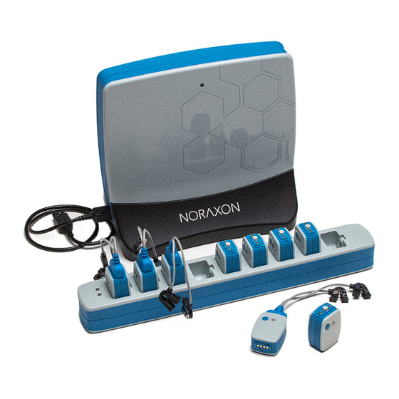
Ultium EMG Hardware User Manual 5 Setting up the Hardware 5.1 System Unboxing The Ultium System is packed within a reinforced padded box for storage and protection during transport. Upon arrival, carefully remove all contents and verify the following components are present. Figure 2 - EMG Sensor Docking Station (part #883) Figure 1 - Ultium Receiver (part #880) Figure 4 - Ultium EMG Smart Lead (part # 842) - Page 12 Double side tape samples (part #842C) Sample electrodes (typically dual electrodes (part #272) Ultium User Manual (part #P-8808) Accessories If additional accessories have been included, please see Section 14, Appendix E of this User Manual, or www.noraxon.com for more information. (Rev J)
-
Page 13: Ultium Receiver Overview
Ultium EMG Hardware User Manual 5.2 Ultium Receiver Overview The below section will over the key components of the Ultium system receiver, sensor, and charging dock. Additional information can be found around the indicators and operation of the system in the following sections. -
Page 14: Ultium Emg Sensor Overview
Ultium EMG Hardware User Manual 5.3 Ultium EMG Sensor Overview EMG Sensor (Front & Top) 1. 1. 1. 1. Status LED Status LED – Sensor operational indicator flashes green when Status LED Status LED measuring. Solid Yellow when charging. 2. 2. 2. 2. Power Button Power Button –... -
Page 15: Hardware Setup Instructions
Ultium EMG Hardware User Manual 5.4 Hardware Setup Instructions Step 1 Insert the USB-B (smaller) end of the USB cable (CBL2) into the USB connector on the rear of the Ultium Receiver (880). Insert the opposite end of the USB cable into an available USB port on the computer. -
Page 16: Installing The Companion Software - Myoresearch™ 3
Ultium EMG Hardware User Manual 5.5 Installing the companion Software – myoResearch™ 3 To utilize the full functionality of the Ultium EMG system, and ensure the system has updated drivers, Noraxon’s myoResearch 3 needs to be installed on the computer. -
Page 17: Configuring The Hardware
Follow the below instructions to update the receiver firmware, sensor firmware, and populate sensors to prepare for a data collection. Step 1 Open MR3, typically listed under Noraxon -> Click on the Hardware Setup Hardware Setup button in the upper... - Page 18 Ultium EMG Hardware User Manual Note: Firmware updates for the Receiver will be indicated here, if they are required. Step 4 Click the Sensors Tab. Place all Ultium Sensors into the chargers and attach the chargers to the Ultium Receiver. If you have any non-EMG Smart Leads, attach them to any EMG sensors.
-
Page 19: Configuration Using Ultium Smart Leads
Ultium EMG Hardware User Manual 5.7 Configuration using Ultium Smart Leads Make sure the Smart Lead is connected to the Ultium sensor before choosing Detect Sensors in Charger. The Ultium sensor LED will flash purple 3 times after a Smart Lead is connected and then will resume blinking blue. -
Page 20: Basic Operation Instructions
(Some skin preparation for the reference pad site may be beneficial if the EMG signal exhibits a wandering baseline. See Appendix A) The EMG Sensors can be secured in place using Noraxon supplied double-sided adhesive tape and/or elastic straps. Straps are recommended if dynamic movements are expected. -
Page 21: Recording A Measurement
2 cm spacing for surface EMG electrodes. The 2-pin lead wire connector can be inserted either way into the EMG Sensor to facilitate attachment to the surface electrodes. Noraxon also offers EMG Smart Leads with longer lead wires for special needs. 6.4 Recording a Measurement... -
Page 22: Check For Normal Signal Display With Interface To A Pc
Electromyography recordings are depending on many best practice standards to ensure ideal signal quality. Within the Noraxon myoResearch platform, standard procedures and best practice functionality has been built to assist the practitioner with identifying their current signal quality. With the Ultium system, a live signal status monitor provides real-time information for practitioners to understand the current recording conditions. - Page 23 EMG signal. 6.7.6 Related Software Measurement Tools Within the Noraxon myoResearch software is a suite of tools that can be used during EMG measurements. Below is a list of the most used features for electromyographic recordings. Additional information around more advanced features can be found on www.noraxon.com...
-
Page 24: Record Signal As Desired
Ultium EMG Hardware User Manual Measure EMG Impedance - - - - Impedance Check Measure EMG Impedance Impedance Check Measure EMG Impedance Measure EMG Impedance Impedance Check Impedance Check To check the impedance of the signal coming through the sensor before measuring, make sure the subject is still and select Measure EMG Impedance Measure EMG Impedance Measure EMG Impedance. -
Page 25: Additional Ultium Emg Settings And Features
7.1.2 MR3 Sync Setup Ultium Receiver Sync is set up in the MR3 software, in Hardware Setup, which is found under the General tab. To enable Sync, simply check the Use Noraxon MyoSync checkbox. (Rev J) -
Page 26: Channel Operation
Ultium supports measuring up to 32 channels via 2 separate 16 channel systems. Insert both systems into the Hardware Setup, making sure to set each receiver to a different RF Network number. Use of the Noraxon MyoSync device is also recommended to synchronize the data streams of the 2 devices. 7.3 Lossless Data Recovery The Ultium System supports “lossless”... -
Page 27: Ultium Internal Inertial Measurement Unit (Imu)
Ultium EMG Hardware User Manual Selection of ‘Offline data recovery’ will then provide you with a list of all records that have lost data. Select each record that you would like to recover at this time. Place all of the sensors (#810) in the sensor docking station (#883), connect the docking ... - Page 28 Ultium EMG Hardware User Manual 7.4.2 Enabling the Internal Accelerometer To activate the accelerometer data channels for a recording select the + + + + next to the name of the sensor within the Hardware setup screen found on the Home tab. This feature is available for sensors with no SmartLeads attached.
-
Page 29: Signal Processing For Amplitude Normalization
7.5 Signal Processing for Amplitude Normalization The companion software program, MR3, supports real-time and post-processing amplitude normalization of the EMG signal. To view the instructions and options for completing this process in MR3, refer to the supplemental MR3 training material at Noraxon.com (Rev J) -
Page 30: Maintenance
Ultium EMG Hardware User Manual Maintenance 8.1 Consumable Items The consumable items listed here for use with your Ultium system are designed for one-time use. It is suggested to regularly restock your supply to have available product when needed. Part No. Part No. - Page 31 Ultium EMG Hardware User Manual Step 2 Insert power supply (PSU1) barrel connector into the jack of the Ultium Receiver. Insert the EMG Sensor Charger Power Source into a power strip (recommended) or into the wall outlet (mains). Step 3 Connect the Receiver to the Sensor Docking Station (883).
-
Page 32: Companion Software Updates
8.3 Companion Software Updates Perform a backup of the data folders to a separate drive as a precaution. Click on the Patch/Update link provided in the email or as given on the Noraxon website. Download the Patch/Update file. - Page 33 Ultium EMG Hardware User Manual 8.5.2 Battery Replacement Procedures The EMG sensor battery packs may not be replaced by the user. Only qualified Noraxon technical personnel may perform maintenance. Your Ultium purchase comes with free battery replacement for life. To initiate a Battery Replacement Form, visit the Support section at Noraxon.com.
-
Page 34: Troubleshooting, Fault Diagnosis
(esp. at long distances) of-sight relationship between sensor and Receiver 9.2 Website Link to FAQ Answers to frequent questions can be found at Noraxon’s Frequently Asked Questions (FAQ) website page at this link: https://www.noraxon.com/support-learn/technical-support/faqs/ Other educational material is available at this link:... -
Page 35: Radio Considerations
Ultium EMG Hardware User Manual https://www.noraxon.com/support-learn/technical-support/ 9.3 Radio Considerations The Ultium radio system operates in the 2400 MHz ISM (Industrial, Scientific and Medical) radio band reserved for use in most countries of the world. The radio transfers data digitally using a proprietary wireless sensor protocol. -
Page 36: Support, Service, And Repair
- - - forwarder. not a freight not a freight forwarder. forwarder. Using a freight-forwarder incurs additional brokerage fees. If a package is forwarder. shipped to Noraxon via a carrier other than the ones listed above, it may be refused. (Rev J) -
Page 37: Taking Product Out Of Operation
Ultium EMG Hardware User Manual 11 Taking Product out of Operation 11.1 Disposal of Equipment and Batteries The EMG Sensors contain Li-Polymer batteries, which may be hazardous if disposed of incorrectly. Please check with the governing authorities in your location before disposing of the Ultium Receiver and its contents. -
Page 38: Technical Information
Ultium EMG Hardware User Manual 12 Technical Information 12.1 Theory of Operation The Ultium wireless system is based on a pre-certified transceiver module. This radio module operates in the 2.4 GHz bands with an output power level of < 100 mW and is based on a proprietary frequency hopping protocol. - Page 39 Ultium EMG Hardware User Manual RF emissions The Ultium System must emit electromagnetic energy in Group 2 CISPR 11 order to perform its intended function. Nearby electronic equipment may be affected. RF emissions Class A The Ultium System is suitable for use in all establishments CISPR 11 other than domestic establishments and those directly Harmonic Emissions...
- Page 40 Ultium EMG Hardware User Manual Portable and mobile RF communications equipment should be used no closer to any part of the Ultium System, including cables, than the recommended separation distance calculated from the equation applicable to the frequency of the transmitter.
- Page 41 Ultium EMG Hardware User Manual Recommended separation distances between portable and mobile RF communications equipment and the Ultium System The Ultium System is intended for use in an electromagnetic environment in which radiated RF disturbances are controlled. The customer or the user of the Ultium System can help prevent electromagnetic interference by maintaining a minimum distance between portable and mobile RF communications equipment (transmitters) and the Ultium System as recommended below, according to the maximum output power of the communications equipment.
-
Page 42: Appendices
Ultium EMG Hardware User Manual 13 Appendices 13.1 Appendix A – Product Specifications Expected Useful Lifetime Both the Ultium Receiver (880) and EMG Sensors (810) have a usable life of seven years. The EMG sensors (#810) operate with a rechargeable Lithium Ion battery. The battery capacity will decline with ongoing use and require replacement after 300+ discharge/charge cycles to preserve the device’s rated 8 hours of operating time. - Page 43 Ultium EMG Hardware User Manual Ultium Charging Dock Ultium Charging Dock Ultium Charging Dock Ultium Charging Dock Dimensions Dimensions Dimensions Dimensions 10.3” L x 1.4” W x 1.1” H (26.1 cm L x 3.6 cm W x 2.9 cm H) Weight Weight Weight...
- Page 44 Ultium EMG Hardware User Manual Ambient Temperature: 0C to 38C Relative Humidity: 10% to 100% Atmospheric Pressure: 70kPa to 107 kPa Environmental Conditions for Storage and Transport Ambient Temperature: -40C to +70C Relative Humidity: 10% to 100% ...
-
Page 45: Appendix B - Use Of Disposable Electrodes
EMG signal may be affected. Also, sometimes the electrode adhesive may not adhere to the skin as well when it is reapplied. Noraxon strongly recommends against the use of dried out electrodes that are re-wetted with electrode gel. - Page 46 Ultium EMG Hardware User Manual pressed onto the electrode after the electrode has been applied. It will also prevent the electrode gel from seeping out. Additionally, this method will prevent unattached leads from coming into accidental contact with other conductive objects. 5.
-
Page 47: Appendix C - Radiation Exposure Information Regarding Use Of Emg Sensors
(next to the person’s head). At present, Noraxon identifies no restrictions on use and placement of the EMG sensors on any portion of the human body. The EMG sensors operate at radio frequencies known to effect older style pacemakers. -
Page 48: Appendix D - Radio Regulatory Statements
Ultium EMG Hardware User Manual 13.4 Appendix D – Radio Regulatory Statements FCC Statement This device complies with part 15 of the FCC rules. Operation is subject to the following two conditions: (1) This device may not cause harmful interference, and (2) this device must accept any interference received, including interference that may cause undesired operation. -
Page 49: Appendix E - Ultium Smartlead Specifications
Ultium EMG Hardware User Manual 13.5 Appendix E – Ultium SmartLead Specifications Model 802 Footswitch 4-zone resistive input with On/Off output. Supports both individual FSR (Force Sensitive Resistors) and insoles. Sensitivity setting to support patients with different body weights. Binary-weighted output voltages for each sensor location are summed for final output voltage. Sample Rate: 2000/4000Hz Output voltages for MR3 and analog outputs: Heel: 0.266V... - Page 50 Ultium EMG Hardware User Manual Analog Output scale factor: 9.524 mV/lbf Model 821 100 LbF Force Sensor Input Channels: 1 Sample Rate: 2000/4000Hz Input Range: +/- 100 lbf (+/- 445 N) Resolution: 0.016 lbf Analog Output scale factor: 9.524 mV/lbf Model 824 Local Pressure Sensor Input Channels: 1 Sample Rate: 2000/4000Hz...
-
Page 51: Appendix F - Ultium Analog Output Module (Model 881)
Ultium EMG Hardware User Manual 13.6 Appendix F – Ultium Analog Output Module (Model 881) The Ultium Analog Output Box can be used in order to transmit data, collected from the Ultium System, to a 3 party software/program in real-time. This device can be used to connect the Ultium receiver (via one of three auxiliary ports on the back of the receiver) to a 3 party Data Acquisition Unit (DAQ) via a 25 Pin Male to Female Cable (Part #291D).
Need help?
Do you have a question about the Ultium EMG System and is the answer not in the manual?
Questions and answers