Table of Contents
Advertisement
Available languages
Available languages
Quick Links
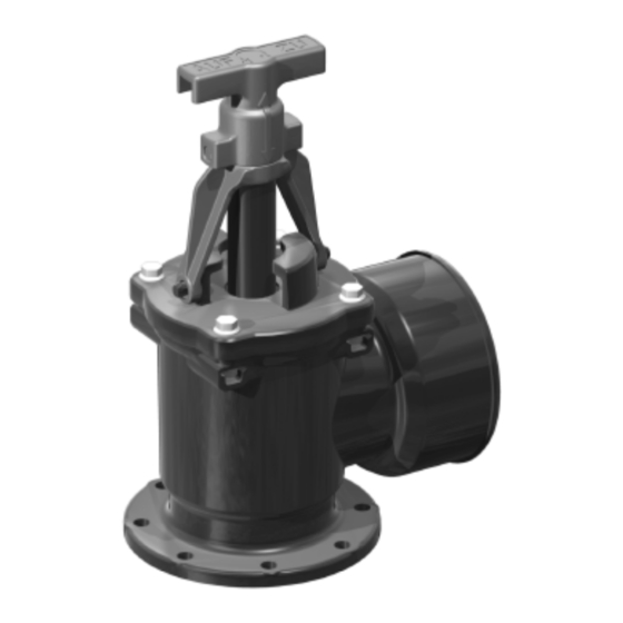
ANLEITUNG FÜR EINBAU BEDIENUNG UND WARTUNG
KESSEL - Absperreinrichtung
für KESSEL-Hebeanlagen Aqualift
für fäkalienhaltiges und fäkalienfreies Abwasser
Installation
Inbetriebnahme
der Anlage wurde durchgeführt von Ihrem Fachbetrieb:
Name/Unterschrift
Datum
-F
®
Best. Nr. 28 683, 28 694
Produktvorteile
Einfache Montage
Drehbarer Druckleitungsanschluß
Schnelle Bedienung
Hohe Druckfestigkeit
Einweisung
Ort
Stempel Fachbetrieb
Seite 1-12
Page 13-24
Änderungsstand: 11/2011
Sachnummer:
240-060
Techn. Änderungen vorbehalten
Advertisement
Chapters
Table of Contents

Subscribe to Our Youtube Channel
Related Manuals for Kessel 28 683


Summary of Contents for Kessel 28 683
- Page 1 ANLEITUNG FÜR EINBAU BEDIENUNG UND WARTUNG KESSEL - Absperreinrichtung für KESSEL-Hebeanlagen Aqualift ® für fäkalienhaltiges und fäkalienfreies Abwasser Seite 1-12 Best. Nr. 28 683, 28 694 Page 13-24 Produktvorteile Einfache Montage Drehbarer Druckleitungsanschluß Schnelle Bedienung Hohe Druckfestigkeit Installation Inbetriebnahme Einweisung der Anlage wurde durchgeführt von Ihrem Fachbetrieb:...
- Page 2 Diese Bedienungsanleitung muss ständig an der Anlage vorhanden sein. Sehr geehrter Kunde, wir freuen uns, dass Sie sich für ein Produkt von KESSEL entschieden haben. Die gesamte Anlage wurde vor Verlassen des Werkes einer strengen Qualitätskontrolle unterzogen. Prüfen Sie bitte dennoch sofort, ob die Anlage vollständig und unbeschädigt bei Ihnen angeliefert wurde.
-
Page 3: Table Of Contents
Inhaltsverzeichnis ......................Seite 1. Sicherheitshinweise ......................Seite 2. Allgemeines ......................Seite 3. Technische Daten ......................Seite 4. Einbau und Montage ......................Seite 5. Funktion und Bedienung ......................Seite 6. Inspektion und Wartung ......................Seite 7. Gewährleistung ......................Seite 8. Ersatzteile... -
Page 4: Allgemeines
2. Allgemeines Die KESSEL-Absperreinrichtung ist ein in- Für die bestimmungsgemäße Verwendung Abmessungen der Absperreinrichtung tegrales oder separates Zubehör zu den der Absperreinrichtung müssen die Hebe- KESSEL-Hebeanlagen Aqualift -F für fäka- anlagen der im Abschnitt „Einbau und Mon- ® lienhaltiges und fäkalienfreies Abwasser zur tage“... -
Page 5: Technische Daten
3. Technische Daten Abmessungen der Absperreinrichtung eingebaut an KESSEL-Hebeanlagen Aqualift ® Einzelanlage (Abb. 3) und Doppelanlage (Abb. 4) Abb. 3 Abb. 4... - Page 6 3. Technische Daten Einbau und Montage der Absperreinrichtung bis Baujahr 05/2009 hat durch qualifiziertes Fachpersonal zu er- folgen. Für die Montage ist sicherzustellen: ➤ Trennung der Hebeanlage vom Netz Sicherungs- ➤ Ausschluß von Abwasserzufluß schrauben ➤ umsichtiges Arbeiten mit den ggf. vorhan- denen Verschmutzungen zur Sicherstel- lung der Hygiene (Schutzkleidung, nicht Rauchen, Essen und Trinken etc.)
-
Page 7: Einbau Und Montage
4. Einbau und Montage Für den sicheren Verbau empfiehlt sich das ACHTUNG: ➤ Das T-Stück bei Doppelanlagen darf Einfetten der Dichtungen. Anschließend wird die Absperreinrichtung wieder analog nur in senkrechter Position (siehe Ab- bildungen 6 und 8) montiert werden. den vorher vorhandenen Druckabgangs- Andere Positionen erlauben keine aus- stutzen montiert, wobei auf einen korrekten reichend sichere Verschraubung und... - Page 8 4. Einbau und Montage Die fertig umgebaute Hebeanlage sieht beispielhaft wie folgt aus: Abb. 10 Abb. 11...
-
Page 9: Funktion Und Bedienung
Absperrung der Druckleitung der seiner Position gesichert (Abb. 12). stand spürbar wird (Abb. 14). Die Absperr - KESSEL-Hebeanlagen für deren Inspektion einrichtung ist nun verschlossen (Abb. 15). und Wartung, beispielsweise zur schnellen Zum Verschließen der Absperreinrichtung ist Demontage und Reinigung der Rück- der Arretierungshebel (A) um 90°... -
Page 10: Inspektion Und Wartung
1. Ist eine Lieferung oder Leistung mangelhaft, frist neu zu laufen, jedoch nur im Umfang der Betrieb entsprechend den aktuell gültigen so hat KESSEL nach Ihrer Wahl den Mangel Neulieferung. Einbau- und Bedienungsanleitungen und den durch Nachbesserung zu beseitigen oder eine Es wird nur für neu hergestellte Sachen eine... -
Page 11: Ersatzteile
8. Ersatzteile Pos.Nr. Menge Teile Nr. Benennung 240-053 Winkelgehäuse 110 240-035 ZSB Kegelverschluss 240-027 O-Ring 240-058 Sich. Skt. Schraube M6 240-059 Sich. Skt. Mutter M6 Verbindung zur Hebeanlage* Pos.Nr. Menge Teile Nr. Benennung 240-037 O-Ring 240-038 Sich. Skt. Schraube M8 240-039 Sich. - Page 12 Rückstauverschlüsse Hebeanlagen Abläufe / Duschrinnen Abscheider -Fettabscheider -Öl-/ Benzin-/Koaleszenzabscheider -Stärkeabscheider -Sinkstoffabscheider Kleinkläranlagen Schächte Regenwassernutzung...
- Page 13 INSTALLATION OPERATION AND MAINTENANCE INSTRUCTIONS KESSEL Closure Valve for KESSEL Aqualift -F lifting stations for wastewater with or without sewage ® Order Nr. 28 683, 28 694 Product Advantages Quick installation Rotatable outlet connection Easy operation High pressure resistance Installation...
- Page 14 This instruction handbook must be available at all times in the station. Dear customer, We are happy, you decided to choose a product made by KESSEL. Before leaving the factory the whole station has been subject to a strict quality control. However, we kindly ask you to check whether the station has been delivered completely and without any damage.
- Page 15 Table of contents ......................Page 1. Safety Instructions ......................Page 2. General ......................Page 3. Technical Data ......................Page 4. Installation and Assembly ......................Page 5. Operation ......................Page 6. Inspection and Maintenance 7- Warranty Page ......................Page 7. Replacement parts...
-
Page 16: General
2. General The KESSEL closure valve is available se- InIn order for the KESSEL closure valve to Closure valve dimensions parately as an accessory or may be already operate properly it should only be connec- integrated in a KESSEL Aqualift F lifting sta- ted to the appropriate KESSEL lifting stati- tion for wastewater with or without sewage. -
Page 17: Technical Data
3. Technical Data KESSEL Closure Valve dimension installed on an KESSEL Aqualift ® F lifting station Il. 3 shows a single pumpAqualift ® Il. 4 shows a twin pump Aqualift ® ill. 3 ill. 4... - Page 18 3. Technical Data A licensed installation company should in- For models up to and incl. May 2009 stall the closure valve on the Aqualift F lifting station. Insallation requires the following ➤ Disconnecting the Aqualift F lifting station Safety bolts from its power source ➤...
-
Page 19: Installation And Assembly
4. Installation and Assembly Gaskets should be properly lubricated befo- ATTENTION: ➤ The T-section on twin pump lifting stati- re the closure valve is installed. Once the clo- sure valve has been installed, it should be ons should only be installed in the ver- tical position (see Illustrations 6 and 8). - Page 20 4. Installation and Assembly After the closure valve has been installed on a single or twin pump KESSEL Aqualift ® F Lifting Station – it should look like one one of the units shown below: ill. 10 ill. 11...
-
Page 21: Operation
5. Operation The closure valve makes it possible to ea- To close the closure valve first lower the sa- recessed plastic holders. The closure valve sily close off the outlet pressure pipe before fety lock (A) 90 degrees to the horizontal po- now is in the closed / shut off position (Ill. -
Page 22: Inspection And Maintenance
1 liter of water should pass through the clo- 7. Warranty 1. In the case that a KESSEL product is de- fective product refers only to the product or A requirement of this additional warranty is fective, KESSEL has the option of repairing... -
Page 23: Replacement Parts
9. Replacement Parts Pos.Nr. Amount Article Number Description 240-053 90 degree outlet housing DN 100 240-035 Closure assembly 240-027 O-ring 240-058 Securing bolts M6 240-059 Securing nuts M6 Connection with lifting station* Pos.Nr. Amount Article Number Description 240-037 O-ring 240-038 Securing bolts M8 240-039 Securing nuts M8... - Page 24 Backwater protection Lifting Stations and pumps Drains and shower channels Separators -Grease Separators -Oil-/ Fuel-/Coalescence Separators -Starch Separators -Sediment Separators Septic Systems Inspection Chambers Rainwater Management Systems...
Need help?
Do you have a question about the 28 683 and is the answer not in the manual?
Questions and answers