Johnson Controls FEC26 Series Installation Instructions Manual
Field equipment controllers
Hide thumbs
Also See for FEC26 Series:
- Installation instructions manual (17 pages) ,
- Installation manual (25 pages) ,
- Installation instructions manual (29 pages)
Table of Contents
Advertisement
FEC26 Field Equipment Controllers Installation Instructions
MS-FEC2611-x, MS-FEC2621-x, MS-FEC2611-xET
Application
The FEC26 controllers are part of the Metasys® system
Field Equipment Controller (FEC) family. These
controllers run pre-engineered and user-programmed
applications and provide the inputs and outputs required
to monitor and control a wide variety of HVAC and other
facility equipment.
The FEC controllers operate on an RS-485 BACnet®
Master-Slave/Token-Passing (MS/TP) Bus as BACnet
Application Specific Controllers (B-ASCs) and integrate
into Johnson Controls® and third-party BACnet systems.
The FEC26 controller is available with or without an
integral LCD and push button user interface.
Important: In Metasys system smoke control
applications, use only the MS-FEC2611-0U
and MS-FEC2621-0U at Metasys Release
8.1 that are UL 864 UUKL/UUKLC 10th
Edition Smoke Control Listed. For Metasys
system smoke control applications, you
must refer to the Metasys System UL 864
UUKL Tenth Edition Smoke Control System
Technical Bulletin (LIT-12012487) for
detailed requirements and procedures for
installing, commissioning, and operating UL
864 UUKL Listed Metasys system devices.
The UL 864 UUKL listing for Smoke Control
Equipment is voided if (1) you do not use
the required software tools at the required
versions; or (2) you do not meet the
requirements or do not follow the
procedures as documented in the Metasys
System UL 864 UUKL Tenth Edition Smoke
Control System Technical Bulletin
(LIT-12012487).
Switchable Communications
Protocols
By default, the Metasys® system FEC Family Controllers
and network sensors communicate using either the
standard BACnet protocol based on the ANSI/ASHRAE
135-2004, or the BACnet/IP protocol.
The BACnet protocol is a standard for ANSI, ASHRAE,
and the International Standards Organization (ISO) for
building controls.
FEC26 Field Equipment Controllers Installation Instructions
Part No. 24-10143-144, Rev. L
Refer to the
QuickLIT website
FEC, VMA16, VMA18, and most IOM field controllers are
BTL-listed as BACnet Application Specific Controllers
(B-ASCs). FAC Field Controllers and the VMA1930 Field
Controller are BTL-listed as BACnet Advanced Application
Controllers (B-AACs). The NS Series Sensors are
BTL-listed as BACnet Smart Sensors (B-SSs).
Release 10.1 and later of the Controller Configuration
Tool (CCT) can be used to switch the Field Bus
communications protocol in supported FEC Family Field
Controllers to be either the standard BACnet MS/TP or
the N2 protocol. All new controllers use BACnet MS/TP
as the default communications protocol. Switchable
communications protocols in the MS/TP models provide
a cost-effective upgrade and modernization path for
customers with existing N2 controllers.
The N2-capable FEC Family Controllers can be used as
functional replacements for legacy N2 controllers. The
N2-capable FEC Family Controllers:
•
have the input and output (I/O) quantities and
characteristics of the FEC Family Controllers
•
must be programmed with CCT, which has similar,
but not identical programming capabilities as
HVACPro, GX9100, GPL, and other legacy tools
•
support SA Bus devices
•
support WRZ wireless sensors from the controller
using the WRZ-7860 receiver (most models)
•
are available in Buy American versions (most models)
•
are listed for UL864 UUKL/UUKLC (some models).
N2 is supported as part of the Metasys® Tenth Edition
listing for Smoke Control System Equipment. For
details, refer to the Metasys System UL 864 10th
Edition UUKL/ORD-C100-13 UUKLC Smoke Control
System Technical Bulletin (LIT-12012487).
The N2-capable controllers:
•
do not support Zone Bus (for example, TMZ sensors
and M100 actuators) or XT-Bus (System 91) devices
(for example, XT, XTM, and XP modules)
•
do not support a wireless connection to the N2 bus
•
do not support NxE passthrough
Issued November 2017
for the most up-to-date version of this document.
1
Advertisement
Table of Contents

Subscribe to Our Youtube Channel
Related Manuals for Johnson Controls FEC26 Series


Summary of Contents for Johnson Controls FEC26 Series
- Page 1 Application Specific Controllers (B-ASCs) and integrate Controllers to be either the standard BACnet MS/TP or into Johnson Controls® and third-party BACnet systems. the N2 protocol. All new controllers use BACnet MS/TP The FEC26 controller is available with or without an as the default communications protocol.
-
Page 2: North American Emissions Compliance
North American Emissions Mounting Observe these guidelines when mounting a field Compliance controller: • Ensure the mounting surface can support the Canada controller, DIN rail, and any user-supplied enclosure. This Class (A) digital apparatus meets all the • Mount the controller horizontally on 35 mm DIN rail requirements of the Canadian Interference-Causing whenever possible. -
Page 3: Din Rail Mount Applications
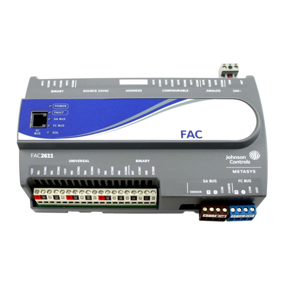
to the wall or surface in a proper mount position and DIN Rail Mount Applications mark the hole locations through the mounting clips. Mounting the field controller horizontal on 35 mm DIN rail 3. Drill holes in the wall or surface at the marked is the preferred mounting method. - Page 4 Figure 3: FEC2621 Physical Features Table 1: FEC2621 Physical Features Callout Physical Feature: Description and References Binary Output (BO) Source Power Selection Jumper Pin Blocks, 3 – BO Jumper Pin Blocks. See Table 4 for more information. Device Address DIP Switch Block. See Setting the Device Addresses for more information.
- Page 5 Wiring FC Bus Terminal Block The FC Bus terminal block is a blue, removable, 4-terminal plug that fits into a board-mounted jack. Risk of Electric Shock: Disconnect the power supply before making electrical connections to avoid electric Wire the removable FC bus terminal block plugs on the shock.
- Page 6 Figure 5: SA Bus Terminal Block Wiring Sensor Port The Sensor (SA Bus) port on the bottom of the controller () is an RJ-12, 6-position modular jack that provides a connection for the Wireless Commissioning Converter, the VAV Balancing Tool, specified network sensors, or other SA Bus devices with RJ-12 plugs.
-
Page 7: Wireless Network Applications
UUKL/UUKLC Listed Metasys system devices. Termination Details A set of Johnson Controls® termination diagrams provides details for wiring inputs and outputs to the controllers. See the figures in this section for the applicable termination diagrams. Table 2: Termination Details Type of Field Device... - Page 8 Table 2: Termination Details Type of Field Device Type of Termination Diagrams Input/Output Voltage Input - Internal Source Voltage Input (Self-Powered) Current Input - External Source (Isolated) Current Input - Internal Source (2-wire) Current Input - Internal Source (3 wire) Current Input - External Source (in Loop) FEC26 Field Equipment Controllers Installation Instructions...
- Page 9 Table 2: Termination Details Type of Field Device Type of Termination Diagrams Input/Output Feedback from EPP-1000 Dry Contact (Binary UI or BI Input) 0–10 VDC Output to CO or AO Actuator (External Source) 0–10 VDC Output to CO or AO Actuator (Internal Source) 4–20 mA Output to...
- Page 10 Table 2: Termination Details Type of Field Device Type of Termination Diagrams Input/Output 4–20 mA Output to CO or AO Actuator Voltage (Analog Output) Analog Output (Current) 24 VAC Triac Output CO or AO (Switch Low, External Source) Incremental Control to CO or AO Actuator (Switch Low, Externally Sourced)
- Page 11 Table 2: Termination Details Type of Field Device Type of Termination Diagrams Input/Output Incremental Control to Actuator (Switch Low, Externally Sourced) 24 VAC Binary Output (Switch Low, Externally Sourced) Incremental Control to Actuator (Switch High, Externally Sourced) 24 VAC Binary Output (Switch High, Externally Sourced) Network Stat with...
- Page 12 Table 2: Termination Details Type of Field Device Type of Termination Diagrams Input/Output Network Stat with SA Bus Terminals Addressable Network Stat with SA Bus Terminals (Fixed Address = 199) FEC26 Field Equipment Controllers Installation Instructions...
-
Page 13: Terminal Wiring Guidelines, Functions, Ratings, And Requirements
FEC26 Series Point Type Counts per Model The following table shows the different point types and counts available in the FEC2511 and FEC26 and Series controllers. Table 3: FEC26 Series Point Type Counts per Model Point Types Signals Accepted (Asia Only model) -
Page 14: Fec26 I/O Wiring Ratings And Requirements Table
FEC26 I/O Wiring Ratings and Requirements Table The following table shows the input/output requirements and ratings for the FEC26 Series controllers. Table 4: FEC26 Terminal Blocks, Functions, Ratings, Requirements, and Cables Terminal Block Terminal Label Function, Ratings, Requirements Determine Wire Size and Maximum... - Page 15 Table 4: FEC26 Terminal Blocks, Functions, Ratings, Requirements, and Cables Terminal Block Terminal Label Function, Ratings, Requirements Determine Wire Size and Maximum Label Cable Length BINARY Binary Input - Dry Contact Maintained See Guideline A in Table Mode (Inputs) 0.01 second minimum pulse width Internal 18 V.
- Page 16 Table 4: FEC26 Terminal Blocks, Functions, Ratings, Requirements, and Cables Terminal Block Terminal Label Function, Ratings, Requirements Determine Wire Size and Maximum Label Cable Length BINARY OUTn Binary Output - 24 VAC Triac (External See Guideline C in Table Power Source) (Output) Connects OUTn to OCOMn when Power Selection...
- Page 17 Table 4: FEC26 Terminal Blocks, Functions, Ratings, Requirements, and Cables Terminal Block Terminal Label Function, Ratings, Requirements Determine Wire Size and Maximum Label Cable Length CONFIGURABLE OUTn Analog Output - Voltage Mode (0–10 See Guideline A in Table VDC) (Outputs) 10 VDC maximum output voltage 10 mA maximum output current Required an external load of 1,000 ohms...
-
Page 18: Cable And Wire Length Guidelines
Cable and Wire Length Guidelines Table 5 defines cable length guidelines for the various wire sizes that may be used for wiring low-voltage (<30 V) input and outputs. Table 5: Cable Length Guidelines for Recommended Wire Sizes for Low-Voltage (<30 V) Inputs and Outputs Guideline Wire Size/Gauge and Type Maximum Cable... -
Page 19: Sa/Fc Bus And Supply Power Wiring Guidelines
In addition to the guidelines in Table 6, observe these SA/FC Bus and Supply Power guidelines when wiring an SA or FC bus and the 24 VAC Wiring Guidelines supply power: Table 6 provides information about the functions, ratings, • Run all low-voltage wiring and cables separate from and requirements for the communication bus and supply high-voltage wiring. -
Page 20: Setup And Adjustments
DIP switch block on the controller's cover. Table 7 describes the FC bus and SA bus devices addresses for Johnson Controls MS/TP Note: Metasys field controllers ship with switch 128 ON communications bus applications. and the remaining address switches off rendering... -
Page 21: Setting The N2 Controller Address To Be Greater Than 127
Setting the N2 Controller Address to Table 7: SA/FC Bus Device Address Descriptions be Greater than 127 Device Use on Description N2-configured controllers support the full range of Address possible N2 device addresses provided by the N2 protocol 0 to 3 Reserved addresses for wired slave devices standard (1–255). -
Page 22: Setting The Input And Output Jumpers
Removing the Controller Cover Setting the End-of-Line (EOL) Switch Important: Electrostatic discharge can damage Each controller has an EOL switch, which, when set to controller components. Use proper ON, sets the controller as a terminating device on the electrostatic discharge precautions during bus. -
Page 23: Universal Input Current Loop Jumpers
Setting the current loop jumper to the Enabled position Important: Do not connect an external power source (Figure 13) connects an internal 100 ohm resistor across to a BO when the BO power source jumper the UI terminals, which maintains the 4-20 mA current is in the internal power (INT) position. -
Page 24: Troubleshooting Field Controllers
Repair Information that are UL 864 10th Edition UUKL/ORD-C100-13 UUKLC If a controller fails to operate within its specifications, listed for smoke control, contact the Johnson Controls replace the controller. For a replacement controller, Repair Center in Louisville, Kentucky, at 1-502-671-7312. -
Page 25: Technical Specifications
Table 10: Accessories Ordering Information Product Code Number Description AP-TBK3PW-0 Replacement Power Terminal Blocks, 3-Position, Gray, Bulk Pack of 10 WNC1800/ZFR182x Pro Wireless This system is used for installations that support BACnet/IP but can also coexist with the field Bus System ZFR1800 Series when installed under the same supervisor (i.e., network engine). - Page 26 Protection Class: IP20 (IEC529) Dimensions(Height x Width x Depth) FEC26 Series: 150 x 190 x 53 mm (5-7/8 x 7-1/2 x 2-1/8 in.) including terminals and mounting clips Note: Mounting space requires an additional 50 mm (2 in.) space on top, bottom and front face of controller for easy cover removal, ventilation and wire terminations.
- Page 27 The performance specifications are nominal and conform to acceptable industry standard. For application at conditions beyond these specifications, consult the local Johnson Controls® office. Johnson Controls shall not be liable for damages resulting from misapplication or misuse of its products.
Need help?
Do you have a question about the FEC26 Series and is the answer not in the manual?
Questions and answers