Table of Contents
Advertisement
Quick Links
FEC25 Field Equipment Controller Installation Instructions
MS-FEC2511-0
Application
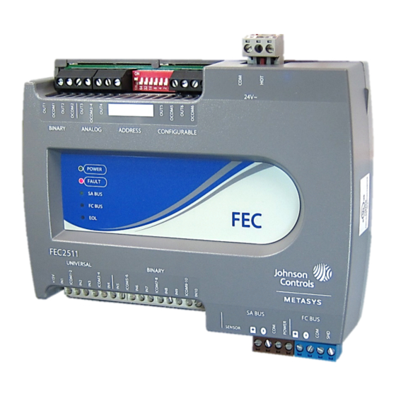
The FEC25 controllers are part of the Metasys® system
Field Equipment Controller (FEC) family. The FEC2511
is a modification of the FEC26 controllers. These
controllers run pre-engineered and user-programmed
applications and provide the inputs and outputs required
to monitor and control a wide variety of HVAC equipment.
Note: The FEC2511 models are not available in all
regions. At this time it is available in Asia and
Europe.
The FEC controllers operate on an RS-485 BACnet®
Master-Slave/Token-Passing (MS/TP) Bus as BACnet
Application Specific Controllers (B-ASCs) and integrate
into Johnson Controls® and third-party BACnet systems.
The FEC2511 is not available with an integrated LCD
and push button user interface. It is slightly smaller than
the FEC26 series, and has fewer input and output options.
The FEC2511 does not support wireless applications.
Switchable Communications
Protocols
By default, the Metasys system FEC family controllers
and network sensors communicate using the standard
BACnet® protocol, based on the ANSI/ASHRAE
135-2004.
The BACnet protocol is a standard for ANSI, ASHRAE,
and the International Standards Organization (ISO) for
building controls.
FEC, IOM, and VMA16 controllers are BTL- tested and
listed as BACnet Application Specific Controllers
(B-ASCs). FAC field controllers are BTL-listed as BACnet
Advanced Application Controllers (B-AACs). The NS
Series Sensors are BTL-listed as BACnet Smart Sensors
(B-SSs).
FEC25 Field Equipment Controller Installation Instructions
Part No. 24-10143-802, Rev. —
Refer to the
QuickLIT website
Release 10.1 of CCT and later can be used to switch the
Field Bus communications protocol in FEC Family Field
Controllers to be either the standard BACnet
Master-Slave/Token-Passing (MS/TP) or the N2 protocol.
BACnet MS/TP is the default communications protocol
for all new controllers. Switchable communications
protocols provide a cost-effective upgrade and
modernization path for customers with existing N2
controllers. The Modernization Guide for Legacy N2
Controllers (LIT-12012005) and the controller-specific
documentation provide installation and commissioning
support and include tips for efficient and safe
replacement. Refer to the N2 Compatibility Options
chapter of the Controller Tool Help (LIT-12011147) for
information about mapping N2 Objects in controllers with
switchable communications protocols.
The N2-capable FEC family controllers can be used as
functional replacements for legacy N2 controllers. The
N2-capable FEC family controllers:
•
have the I/O quantities and characteristics of the FEC
family controllers
•
must be programmed with CCT, which has similar,
but not identical programming capabilities as
HVACPro, GX9100, GPL, and other legacy tools
•
support SA Bus devices
•
support WRZ wireless sensors from the controller
using the WRZ-7860 receiver
•
are available in Buy American versions (most models)
The N2-capable FEC family controllers:
•
do not support Zone Bus (for example, TMZ sensors
and M100 actuators) or XT-Bus (System 91) devices
(for example, XT, XTM, and XP modules)
•
do not support a wireless connection to the N2 bus
•
do not support NxE pass through
•
are not listed for UL864 UUKL. N2 is not supported
as part of the Metasys® 9th Edition listing for Smoke
Control System Equipment
Issued April 2016
for the most up-to-date version of this document.
1
Advertisement
Table of Contents

Related Manuals for Johnson Controls FEC25


Summary of Contents for Johnson Controls FEC25
- Page 1 Application Release 10.1 of CCT and later can be used to switch the The FEC25 controllers are part of the Metasys® system Field Bus communications protocol in FEC Family Field Field Equipment Controller (FEC) family. The FEC2511 Controllers to be either the standard BACnet is a modification of the FEC26 controllers.
-
Page 2: North American Emissions Compliance
(M4 screws or #8 screws) • one 20 cm (8 in.) or longer piece of 35 mm DIN rail and appropriate hardware for DIN rail mount (only) • small straight-blade screwdriver for securing wires in the terminal blocks FEC25 Field Equipment Controller Installation Instructions... -
Page 3: Din Rail Mount Applications
Figure 2: Back of FEC25 Controller Showing Extended Mounting Clips, DIN Rail Channel, and Mounting DIN Rail Mount Applications Dimensions, mm (in.) Mounting the field controller horizontal on 35 mm DIN rail is the preferred mounting method. To mount a controller on 35 mm DIN rail: 1. - Page 4 Sensor Actuator (SA) Bus (RJ-12 6-pin Modular Jack) Binary Input (BI) Terminal Block Universal Inputs (UI) Terminal Block LED Status Indicators Binary Output (BO) Terminal Block Analog Outputs (AO) Terminal Block Cover lift tabs FEC25 Field Equipment Controller Installation Instructions...
- Page 5 4-wire twisted, shielded cable as Figure 3 for terminal block and bus port locations on shown in the following figure. See Table 6 for more the controller. Observe the following guidelines when information. wiring a controller. FEC25 Field Equipment Controller Installation Instructions...
- Page 6 3) is an RJ-12, 6-position modular jack that does not require an earth ground provides a connection for the Wireless Commissioning connection. Converter, the VAV Balancing Tool, specified network sensors, or other SA Bus devices with RJ-12 plugs. FEC25 Field Equipment Controller Installation Instructions...
-
Page 7: Termination Details
Termination Details A set of Johnson Controls® termination diagrams provides details for wiring inputs and outputs to the controllers. See the figures in this section for the applicable termination diagrams. The following table contains termination diagrams for the FEC2511. Table 2: Termination Details... - Page 8 FAC3611 does (External not have CO. Source) 0–10 VDC CO or AO Output to Note that Actuator FAC3611 does (Internal Source) not have CO. Voltage (Analog Output) 24 VAC Triac Output (Switch Low, External Source) FEC25 Field Equipment Controller Installation Instructions...
- Page 9 24 VAC Binary Output (Switch Low, Externally Sourced) (Triac Jumpers Where Applicable) 24 VAC Binary Output (Switch High, Externally Sourced) (Triac Jumpers Where Applicable) Incremental Control to Actuator (Switch High, Externally Sourced) (Triac Jumpers Where Applicable) FEC25 Field Equipment Controller Installation Instructions...
- Page 10 Note: The bottom jack (J2) on the TE-700 and TE-6x00 Series Sensors is not usable as a zone bus or a Sensor/Actuator bus (SAB) connection. Network Stat SA Bus with Terminals Addressable Network Stat SA Bus with Terminals (Fixed Address = 199) FEC25 Field Equipment Controller Installation Instructions...
-
Page 11: Terminal Wiring Guidelines, Functions, Ratings, And Requirements
Inputs/outputs with cables less than 30 m (100 ft) typically do not require an offset in the software setup. Cable runs over 30 m (100 ft) may require an offset in the input/output software setup. FEC25 Field Equipment Controller Installation Instructions... - Page 12 Internal 12 V. 15k ohms pull up ICOMn Universal Input Common for Same as (Universal) INn all Universal Input terminals Note: All Universal ICOMn terminals share a common, which is isolated from all other commons. FEC25 Field Equipment Controller Installation Instructions...
- Page 13 Voltage Mode applications. OCOMn Analog Output Signal Common for all Analog OUT terminals. Note: All Analog Output Common terminals (OCOMn) share a common, which is isolated from all other commons. FEC25 Field Equipment Controller Installation Instructions...
- Page 14 Binary Input common. Binary Output Signal Common All Configurable Outputs (COs) defined as Binary Outputs are isolated from all other commons, including other CO commons. FEC25 Field Equipment Controller Installation Instructions...
- Page 15 2 (Voltage Only) 0–10 VDC Analog Output, Current Mode, 4–20 mA Binary Output (BO) 24 VAC Triac 2 (Ext Power only) Configurable Output (CO) Analog Output, Voltage Mode, 0–10 VDC Binary Output Mode, 24 VAC Triac FEC25 Field Equipment Controller Installation Instructions...
-
Page 16: Cable And Wire Length Guidelines
(in mA) when wiring inputs and outputs. Figure 8: Maximum Wire Length for Low-Voltage (<30V) Inputs and Outputs by Current and Wire Size FEC25 Field Equipment Controller Installation Instructions... -
Page 17: Sa/Fc Bus And Supply Power Wiring Guidelines
Common terminals on controller) 35 VA The SA Bus and FC Bus wiring recommendations in this table are for MS/TP bus communications at 38.4k baud. For more information, refer to the MS/TP Communications Bus Technical Bulletin (LIT-12011034). FEC25 Field Equipment Controller Installation Instructions... -
Page 18: Setup And Adjustments
For example, if the 128 Off) intended device address is 21, set switch 16 to ON first, then set switch 4 ON, followed by switch 1 (16+4+1= 21). See Figure FEC25 Field Equipment Controller Installation Instructions... -
Page 19: Setting The N2 Controller Address To Be Greater Than 127
EOL switch on the controller. Failure to disconnect power before changing a jumper or EOL switch position can result in damage to the controller and void any warranties. FEC25 Field Equipment Controller Installation Instructions... -
Page 20: Setting The End-Of-Line (Eol) Switch
Observe the Status LEDs on the front of the field controller and see Table 8 to troubleshoot the controller. To troubleshoot a local controller display, refer to the DIS1710 Local Controller Display Technical Bulletin (LIT-12011270). FEC25 Field Equipment Controller Installation Instructions... -
Page 21: Repair Information
Note: The ZFR-USBHA-0 replaces the IA OEM DAUBI_2400 ZigBee USB dongle. For additional information on the ZFR-USBHA-0 ZigBee dongle, refer to the ZFR1800 Series Wireless Field Bus System Technical Bulletin (LIT-12011295) or ZFR1800 Series Wireless Field Bus System Quick Reference Guide (LIT-12011630). FEC25 Field Equipment Controller Installation Instructions... -
Page 22: Technical Specifications
Horizontal on single 35 mm DIN rail mount (preferred), or screw mount on flat surface with three integral mounting clips on controller Housing Enclosure material: ABS and polycarbonate, Rating V0 minimum Protection Class: IP20 (IEC529) FEC25 Field Equipment Controller Installation Instructions... - Page 23 The performance specifications are nominal and conform to acceptable industry standard. For application at conditions beyond these specifications, consult the local Johnson Controls® office. Johnson Controls, Inc. shall not be liable for damages resulting from misapplication or misuse of its products.
Need help?
Do you have a question about the FEC25 and is the answer not in the manual?
Questions and answers