Johnson Controls FEC26 Series Installation Manual
Field equipment controllers
Hide thumbs
Also See for FEC26 Series:
- Installation instructions manual (17 pages) ,
- Installation instructions manual (28 pages) ,
- Installation instructions manual (29 pages)
Table of Contents
Advertisement
Application
The FEC26 controllers are part of the Metasys
Field Equipment Controller (FEC) family. These controllers
run pre-engineered and user-programmed applications
and provide the inputs and outputs required to monitor
and control a wide variety of HVAC and other facility
equipment.
The FEC controllers operate on an RS-485 BACnet
TP Bus as BACnet Application Specific Controllers (B-ASCs)
and integrate into Johnson Controls
BACnet systems.
The FEC26 controller is available with or without an
integral LCD and push button user interface.
Important: In Metasys system smoke control
applications, use only the MS-FEC2611-0U and MS-
FEC2621-0U at Metasys Release 8.1 that is UL 864
UUKL/UUKLC 10th Edition Smoke Control Listed. For
Metasys system smoke control applications, you must
refer to the Metasys System UL 864 UUKL Tenth Edition
Smoke Control System Technical Bulletin (LIT-12012487)
for detailed requirements and procedures for
installing, commissioning, and operating UL 864
UUKL Listed Metasys system devices. The UL 864
UUKL listing for Smoke Control Equipment is voided
if (1) you do not use the required software tools
at the required versions; or (2) you do not meet
the requirements or do not follow the procedures
as documented in the Metasys System UL 864 UUKL
Tenth Edition Smoke Control System Technical Bulletin
(LIT-12012487).
Switchable communications protocols
By default, the Metasys system FEC Family Controllers
and network sensors communicate using the standard
BACnet protocol based on the ANSI/ASHRAE 135-2008. The
BACnet protocol is a standard for ANSI, ASHRAE, and the
International Standards Organization (ISO) for building
controls.
FEC, VMA16, and VMA18 are BTL-listed as BACnet
Application Specific Controllers (B-ASCs). FAC Field
Controllers and the VMA1930 Field Controller are BTL-
listed as BACnet Advanced Application Controllers (B-
AACs). The NS Series Sensors are BTL-listed as BACnet
Smart Sensors (B-SSs).
Release 10.1 and later of the Controller Configuration Tool
(CCT) can be used to switch the Field Bus communications
protocol in supported FEC Family Field Controllers to be
either the standard BACnet MS/TP or the N2 protocol.
All new controllers use BACnet MS/TP as the default
communications protocol. Switchable communications
protocols in the MS/TP models provide a cost-effective
FEC26 Field Equipment Controllers Installation
system
®
MS/
®
and third-party
®
upgrade and modernization path for customers with
existing N2 controllers.
The N2-capable FEC Family Controllers can be used as
functional replacements for legacy N2 controllers. The N2-
capable FEC Family Controllers:
• have the input and output (I/O) quantities and
characteristics of the FEC Family Controllers
• must be programmed with CCT
• support SA Bus devices
• support WRZ wireless sensors from the controller using
the WRZ-7860 receiver (most models)
• are available in Buy American versions (most models)
• are listed for UL 864 UUKL/ORD-C100-13 UUKLC 10th
Edition Smoke Control (some models). N2 is now
supported as part of the Metasys 10th Edition listing
for Smoke Control System Equipment. For details, refer
to the Metasys System UL 864 10th Edition UUKL/ORD-
C100-13 UUKLC Smoke Control System Technical Bulletin
(LIT-12012487).
The N2-capable controllers:
• do not support Zone Bus (for example, TMZ sensors
and M100 actuators) or XT-Bus (System 91) devices (for
example, XT, XTM, and XP modules)
• do not support a wireless connection to the N2 bus
• do not support NxE passthrough
North American Emissions Compliance
Canada
This Class (A) digital apparatus meets all the
requirements of the Canadian Interference-Causing
Equipment Regulations.
Cet appareil numérique de la Classe (A) respecte toutes
les exigences du Règlement sur le matériel brouilleur du
Canada.
United States
This equipment has been tested and found to comply
with the limits for a Class A digital device pursuant to
Part 15 of the FCC Rules. These limits are designed
to provide reasonable protection against harmful
interference when this equipment is operated in a
commercial environment. This equipment generates,
uses, and can radiate radio frequency energy and, if not
installed and used in accordance with the instruction
manual, may cause harmful interference to radio
communications. Operation of this equipment in a
residential area may cause harmful interference, in which
case the users will be required to correct the interference
at their own expense.
Guide
Part No. 24-10143-144 Rev. M
2019-10-18
*2410143144M*
(barcode for factory use only)
MS-FEC2611-x, MS-FEC2621-x, MS-
FEC2611-xET
Advertisement
Table of Contents

Related Manuals for Johnson Controls FEC26 Series


Summary of Contents for Johnson Controls FEC26 Series
- Page 1 The FEC controllers operate on an RS-485 BACnet ® • support SA Bus devices TP Bus as BACnet Application Specific Controllers (B-ASCs) • support WRZ wireless sensors from the controller using and integrate into Johnson Controls and third-party ® the WRZ-7860 receiver (most models) BACnet systems.
-
Page 2: Installation
Installation Observe these guidelines when installing a controller: • Transport the controller in the original container to minimize vibration and shock damage. • Verify that all parts shipped with the controller. • Do not drop the controller or subject it to physical shock. -
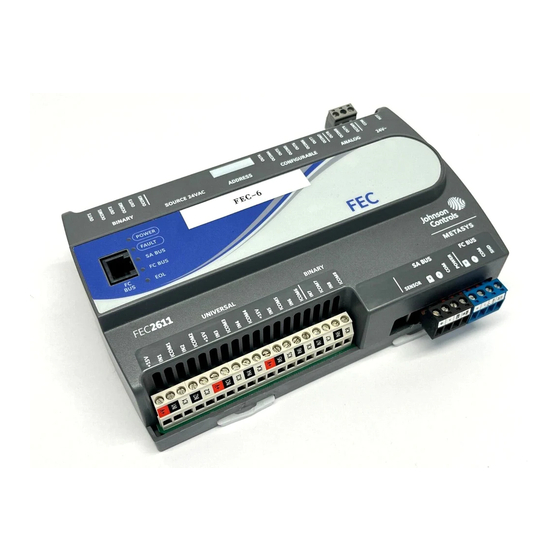
Page 3: Physical Features
Physical features Figure 1: FEC2621 physical features Table 1: FEC2621 Physical Features Callout Physical Feature: Description and References Binary Output (BO) Source Power Selection Jumper Pin Blocks, 3 – BO Jumper Pin Blocks. See Table 3 for more information. Device Address DIP Switch Block. See Setting the device addresses for more information. -
Page 4: Wall Mount Applications
Wall mount applications • Provide for sufficient space around the controller for cable and wire connections for easy cover removal and good ventilation through the controller (50 mm To mount a controller directly on a wall or other flat [2 in.] minimum on the top, bottom, and front of the vertical surface: controller). - Page 5 3 for more information about I/O terminal functions, requirements, and ratings. ATTENTION FC bus terminal block Risque de décharge électrique. The FC Bus terminal block is a blue, removable, 4-terminal plug that fits into a board-mounted jack. Débrancher l'alimentation avant de réaliser tout rac- Wire the removable FC bus terminal block plugs on cordement électrique afin d'éviter tout risque de the controller, and other controllers in a daisy-chain...
- Page 6 Figure 5: SA bus terminal block wiring controller. A DIS1710 Local Controller Display also can be connected to the SA Bus port (but only on models without integral display and push buttons). The Sensor port is connected internally to the SA bus terminal block.
- Page 7 4 (Does not support Current Analog Input, Resistive Mode, 0–2k ohm, RTD Universal Input (UI) Mode) (1k NI [Johnson Controls], 1k PT, A99B SI), NTC (10k Type L, 2.252k Type 2) Binary Input, Dry Contact Maintained Mode Dry Contact Maintained Mode...
- Page 8 Input/Output Terminal Blocks, ratings and requirements The following table shows the input/output requirements and ratings for the controllers. Table 3: Terminal blocks, functions, ratings, requirements, and cables Determine wire size and maximum cable Terminal block label Terminal label Function, ratings, requirements length 15 VDC Power Source for active (3-wire) Same as (Universal) INn...
- Page 9 Table 3: Terminal blocks, functions, ratings, requirements, and cables Determine wire size and maximum cable Terminal block label Terminal label Function, ratings, requirements length Analog Output - Voltage Mode (0–10 VDC) 10 VDC maximum output voltage 10 mA maximum output current Required an external load of 1,000 ohms or more.
-
Page 10: Cable And Wire Length Guidelines
Table 3: Terminal blocks, functions, ratings, requirements, and cables Determine wire size and maximum cable Terminal block label Terminal label Function, ratings, requirements length Analog Output - Voltage Mode (0–10 VDC) 10 VDC maximum output voltage See Guideline A in Table 4. 10 mA maximum output current Required an external load of 1,000 ohms or more. -
Page 11: Communications Bus And Supply Power Wiring Guidelines
Max wire length by current and wire size power terminals; and guidelines for wire sizes, cable types, and cable lengths when wiring the controller's graphic communication buses and supply power. In addition to the guidelines in Table 5, observe these Figure 8: Maximum wire length for low-voltage (<30 guidelines when wiring an SA or FC bus and the 24 VAC V) Inputs and Outputs by current and wire size... -
Page 12: Termination Details
Termination details See the figures in this section for the applicable termination diagrams. A set of Johnson Controls termination diagrams provides details for wiring inputs and outputs to the controllers. Table 6: Termination details Type of Input/ Type of field device... - Page 13 Table 6: Termination details Type of Input/ Type of field device Termination diagrams Output Current Input - External Source (in Loop) Feedback from EPP-1000 Dry Contact (Binary UI or BI Input) 0–10 VDC Output to Actuator (External CO or AO Source) 0–10 VDC Output to Actuator (Internal...
- Page 14 Table 6: Termination details Type of Input/ Type of field device Termination diagrams Output 4–20 mA Output to CO or AO Actuator 4–20 mA Output to CO or AO Actuator Voltage (Analog Output) AO Analog Output (Current) AO 24 VAC Triac Output (Switch Low, External CO or AO Source)
- Page 15 Table 6: Termination details Type of Input/ Type of field device Termination diagrams Output 24 VAC Binary Output (Switch High, Externally CO or AO Sourced) Incremental Control to Actuator (Switch High, CO or AO Externally Sourced) Incremental Control to Actuator (Switch Low, Externally Sourced) 24 VAC Binary Output (Switch Low, Externally...
-
Page 16: Setup And Adjustments
Table 6: Termination details Type of Input/ Type of field device Termination diagrams Output 24 VAC Binary Output (Switch High, Externally Sourced) Network Stat with Phone SA Bus Jack (Fixed Address = 199) Network Stat with SA Bus Terminals Addressable Network Stat with Terminals (Fixed Address SA Bus... -
Page 17: Setting The N2 Controller Address To Be Greater Than 127
ON. Then continue set- Table 7 describes the FC bus and SA bus devices ting lower-numbered switches until the total equals the addresses for Johnson Controls MS/TP communications intended address. For example, if the intended device bus applications. -
Page 18: Removing The Controller Cover
Controller cover removed showing EOL Remove the FC Bus connector from the controller. switch & current jumpers Set the address switch set to the desired N2 address. Figure 10: Controller with cover removed showing Set the address switch segment labeled 128 to EOL switch and jumper positions OFF. - Page 19 Setting the Input and Output Jumpers Figure 12: Example binary outputs and the associated source power jumper positions Binary Output (BO) source power selection jumpers CAUTION Risk of Electric Shock. Disconnect supply power to the field controller before attempting to adjust the Binary Output Source Power Selection Jumpers.
-
Page 20: Setting Up An Integral Or Local Display
Table 8: FEC26 UI Inputs and jumper labels Universal Input label Jumper label on circuit board Setting up an integral or local display FEC2621 models have an integral LCD and push button user interface that allows you to set up and monitor the FEC, the FEC I/O points, and the modules and I/O points connected on the SA bus. -
Page 21: Troubleshooting Field Controllers
Johnson Controls representative. For the MS-FEC2611-0U and MS-FEC2621-0U models that are UL 864 10th Edition UUKL/ORD-C100-13 UUKLC listed for smoke control, contact the Johnson Controls Repair Center in Louisville, Kentucky, at 1-502-671-7312. FEC26 Field Equipment Controllers Installation Guide... - Page 22 Accessories Table 10: Accessories Ordering Information Product Code Number Description MS-DIS1710-0 Local Controller Display (for use with MS-FEC2611 model only) TP-2420 Transformer, 120 VAC Primary to 24 VAC secondary, 20 VA, Wall Plug Transformer, 120/208/240 VAC Primary to 24 VAC Secondary, 40 VA, Foot Mount, 8 in. Primary Leads and Secondary Screw Terminals, Class 2 Y65T31-0 Note: Additional Y6x-x Series transformers are also available.
-
Page 23: Technical Specifications
N2 Open Protocol: N2/FC Bus: 1.0mm (18 AWG) standard 3-wire, twisted, shielded cable recommended between the supervisory controller and field controllers Processor FEC26 Series: H8SX/166xR Renesas 32-bit microcontroller ® Memory 640 KB flash memory and 128 KB RAM FEC26 Series: 6 - Universal Inputs: Defined as 0–10 VDC, 4-20 mA, 0–600k ohm, or Binary Dry Contact... -
Page 24: Product Warranty
Table 11: FEC26 technical specifications FEC26 Series: 150 mm x 190 mm x 53 mm (5-7/8 in. x 7-1/2 in. x 2-1/8 in.) including terminals and mounting clips Dimensions(Height x Width x Depth) Note: Mounting space requires an additional 50 mm (2 in.) space on top, bottom and front face of controller for easy cover removal, ventilation and wire terminations.
Need help?
Do you have a question about the FEC26 Series and is the answer not in the manual?
Questions and answers