Johnson Controls FEC26 Series Installation Instructions Manual
Field equipment
Hide thumbs
Also See for FEC26 Series:
- Installation instructions manual (17 pages) ,
- Installation instructions manual (28 pages) ,
- Installation manual (25 pages)
Table of Contents
Advertisement
FEC26 Field Equipment Controllers Installation Instructions
MS-FEC2611-x, MS-FEC2621-x, MS-FEC2611-x OET,
Application
The FEC26 controllers are part of the Metasys® system
Field Equipment Controller (FEC) family. The FEC2511
is a modification of the FEC26 controllers. These
controllers run pre-engineered and user-programmed
applications and provide the inputs and outputs required
to monitor and control a wide variety of HVAC equipment.
The FEC controllers operate on an RS-485 BACnet®
Master-Slave/Token-Passing (MS/TP) Bus as BACnet
Application Specific Controllers (B-ASCs) and integrate
into Johnson Controls® and third-party BACnet systems.
The FEC26 controller is available with or without an
integral LCD and push button user interface.
Switchable Communications
Protocols
By default, the Metasys system FEC family controllers
and network sensors communicate using the standard
BACnet® protocol, based on the ANSI/ASHRAE
135-2004.
The BACnet protocol is a standard for ANSI, ASHRAE,
and the International Standards Organization (ISO) for
building controls.
FEC, IOM, and VMA16 controllers are BTL- tested and
listed as BACnet Application Specific Controllers
(B-ASCs). FAC field controllers are BTL-listed as BACnet
Advanced Application Controllers (B-AACs). The NS
Series Sensors are BTL-listed as BACnet Smart Sensors
(B-SSs).
Release 10.1 of CCT and later can be used to switch the
Field Bus communications protocol in FEC Family Field
Controllers to be either the standard BACnet
Master-Slave/Token-Passing (MS/TP) or the N2 protocol.
BACnet MS/TP is the default communications protocol
for all new controllers. Switchable communications
protocols provide a cost-effective upgrade and
modernization path for customers with existing N2
controllers. The Modernization Guide for Legacy N2
Controllers (LIT-12012005) and the controller-specific
documentation provide installation and commissioning
support and include tips for efficient and safe
replacement. Refer to the N2 Compatibility Options
chapter of the Controller Tool Help (LIT-12011147) for
information about mapping N2 Objects in controllers with
switchable communications protocols.
FEC26Field Equipment Controllers Installation Instructions
Part No. 24-10143-144, Rev. K
Refer to the
QuickLIT website
The N2-capable FEC family controllers can be used as
functional replacements for legacy N2 controllers. The
N2-capable FEC family controllers:
•
have the I/O quantities and characteristics of the FEC
family controllers
•
must be programmed with CCT, which has similar,
but not identical programming capabilities as
HVACPro, GX9100, GPL, and other legacy tools
•
support SA Bus devices
•
support WRZ wireless sensors from the controller
using the WRZ-7860 receiver
•
are available in Buy American versions (most models)
The N2-capable FEC family controllers:
•
do not support Zone Bus (for example, TMZ sensors
and M100 actuators) or XT-Bus (System 91) devices
(for example, XT, XTM, and XP modules)
•
do not support a wireless connection to the N2 bus
•
do not support NxE pass through
•
are not listed for UL864 UUKL. N2 is not supported
as part of the Metasys® 9th Edition listing for Smoke
Control System Equipment
North American Emissions
Compliance
Canada
This Class (A) digital apparatus meets all the
requirements of the Canadian Interference-Causing
Equipment Regulations.
Cet appareil numérique de la Classe (A) respecte toutes
les exigences du Règlement sur le matériel brouilleur
du Canada.
Issued April 2016
for the most up-to-date version of this document.
1
Advertisement
Table of Contents

Related Manuals for Johnson Controls FEC26 Series


Summary of Contents for Johnson Controls FEC26 Series
- Page 1 SA Bus devices Application Specific Controllers (B-ASCs) and integrate • support WRZ wireless sensors from the controller into Johnson Controls® and third-party BACnet systems. using the WRZ-7860 receiver The FEC26 controller is available with or without an • are available in Buy American versions (most models) integral LCD and push button user interface.
-
Page 2: Installation
• Use shims or washers to mount the controller securely and evenly on the mounting surface. United States • Mount the controller in an area free of corrosive This equipment has been tested and found to comply vapors and observe the Ambient Conditions with the limits for a Class A digital device pursuant to requirements in . -
Page 3: Wall Mount Applications
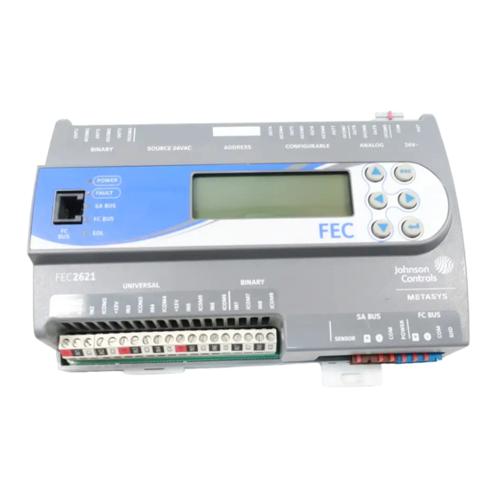
3. Hang the controller on the DIN rail by the hooks at the top of the (DIN rail) channel on the back of the controller (), and position the controller snugly against the DIN rail. 4. Push the bottom mounting clips inward (up) to secure the controller on the DIN rail. - Page 4 Figure 2: Back of FEC26 Controller Showing Extended Mounting Clips, DIN Rail Channel, and Mounting Dimensions, mm (in.) Figure 3: FEC2621 Physical Features Table 1: FEC2621 Physical Features Callout Physical Feature: Description and References Binary Output (BO) Source Power Selection Jumper Pin Blocks, 3 – BO Jumper Pin Blocks. See for more information.
- Page 5 Table 1: FEC2621 Physical Features Callout Physical Feature: Description and References Cover Lift Tab (One of Two). See for more information. Display Navigation Buttons. See . Note: Not available on all FEC models. Liquid Crystal Display (LCD) Display Area Note: Not available on all FEC models. Field Controller (FC) Bus Terminal Block.
- Page 6 Wiring Observe the following guidelines when wiring a controller: Input and Output Terminal Blocks All of the fixed input terminal blocks are mounted on the bottom of the controller and the output terminal blocks are mounted on the top of the controller. See for more Risk of Electric Shock: Disconnect the power supply information about I/O terminal functions, requirements, before making electrical connections to avoid electric...
- Page 7 Figure 5: SA Bus Terminal Block Wiring Sensor Port The Sensor (SA Bus) port on the bottom of the controller () is an RJ-12, 6-position modular jack that provides a connection for the Wireless Commissioning Converter, the VAV Balancing Tool, specified network sensors, or other SA Bus devices with RJ-12 plugs.
-
Page 8: Wireless Network Applications
Field Bus Router Installation Instructions (Part No. 24-10325-10). Termination Details A set of Johnson Controls® termination diagrams provides details for wiring inputs and outputs to the controllers. See the figures in this section for the applicable termination diagrams. Table 2: Termination Details... - Page 9 Table 2: Termination Details Type of Field Device Type of Termination Diagrams Input/Output Voltage Input (Self-Powered) Current Input - External Source (Isolated) Current Input - Internal Source (2 wire) Current Input - Internal Source (3 wire) Current Input - External Source (in Loop) Feedback from EPP-1000...
- Page 10 Table 2: Termination Details Type of Field Device Type of Termination Diagrams Input/Output Dry Contact (Binary UI or BI Input) 0–20 VDC Output to CO or AO Actuator (External Source) 0–10 VDC Output to CO or AO Actuator (Internal Source) 4–20 mA Output to CO or AO Actuator...
- Page 11 Table 2: Termination Details Type of Field Device Type of Termination Diagrams Input/Output Voltage (Analog Output) Analog Output (Current) 24 VAC Triac Output (Switch Low, External Source) Incremental Control to Actuator (Switch Low, Externally Sourced) FEC26Field Equipment Controllers Installation Instructions...
- Page 12 Table 2: Termination Details Type of Field Device Type of Termination Diagrams Input/Output 24 VAC Binary Output (Switch Low, Externally Sourced) Incremental Control to Actuator (Switch High, Externally Sourced) 24 VAC Binary Output (Switch High, Externally Sourced) Network Stat with SA Bus Phone Jack (Fixed Address = 199)
-
Page 13: Terminal Wiring Guidelines, Functions, Ratings, And Requirements
Table 1 provides information and guidelines about the available in the FEC2511 and FEC26 Series controllers. functions, ratings, and requirements for the controller input and output terminals; and references guidelines for Field Equipment Controller (FEC)2511 and FEC26 Series determining proper wire sizes and cable lengths. - Page 14 Point Types Signals FEC2511 FEC26 Point Types Signals FEC2511 FEC26 Accepted (Asia Only Accepted (Asia Only model) model) Universal Analog Input, 4 (Does not Binary Input Dry Contact Input (UI) Voltage Mode, support (BI) Maintained 0–10 VDC Current Mode) Mode Analog Input, Pulse Current Mode,...
- Page 15 Table Mode (0–600k ohms) Internal 12 V. 15k ohms pull up Qualified Sensors: 0-2k ohms potentiometer, RTD (1k Nickel [Johnson Controls® sensor], 1k Platinum, and A99B Silicon Temperature Sensor) Negative Temperature Coefficient (NTC) Sensor (10k Type L, 10k JCI Type II, 2.252k Type II)
- Page 16 Table 3: FEC26 Terminal Blocks, Functions, Ratings, Requirements, and Cables Terminal Block Label Terminal Label Function, Ratings, Determine Wire Size and Requirements Maximum Cable Length BINARY Binary Input - Dry Contact See Guideline A in Table Maintained Mode (Inputs) 0.01 second minimum pulse width Internal 18 V.
- Page 17 Table 3: FEC26 Terminal Blocks, Functions, Ratings, Requirements, and Cables Terminal Block Label Terminal Label Function, Ratings, Determine Wire Size and Requirements Maximum Cable Length ANALOG OUTn Analog Output - Voltage See Guideline C in Table Mode (0–10 VDC) (Outputs) 10 VDC maximum output voltage 10 mA maximum output current...
- Page 18 Table 3: FEC26 Terminal Blocks, Functions, Ratings, Requirements, and Cables Terminal Block Label Terminal Label Function, Ratings, Determine Wire Size and Requirements Maximum Cable Length BINARY OUTn Binary Output - 24 VAC Triac See Guideline C in Table (External Power Source) (Output) Connects OUTn to OCOMn Power Selection Jumper...
- Page 19 Table 3: FEC26 Terminal Blocks, Functions, Ratings, Requirements, and Cables Terminal Block Label Terminal Label Function, Ratings, Determine Wire Size and Requirements Maximum Cable Length CONFIGURABLE OUTn Analog Output - Voltage See Guideline A in Table Mode (0–10 VDC) (Outputs) 10 VDC maximum output voltage 10 mA maximum output current...
-
Page 20: Cable And Wire Length Guidelines
Table 4 defines cable length guidelines for the various Cable and Wire Length wire sizes that may be used for wiring low-voltage (<30V) Guidelines input and outputs. Table 4: Cable Length Guidelines for Recommended Wire Sizes for Low-Voltage (<30V) Inputs and Outputs Guideline Wire Size/Gauge and Type Maximum Cable... -
Page 21: Sa/Fc Bus And Supply Power Wiring Guidelines
In addition to the guidelines in Table 5, observe these SA/FC Bus and Supply Power guidelines when wiring an SA or FC bus and the 24 VAC Wiring Guidelines supply power: Table 5 provides information about the functions, ratings, • Run all low-voltage wiring and cables separate from and requirements for the communication bus and supply high-voltage wiring. -
Page 22: Setup And Adjustments
DIP switch block on the controller's cover. Table 1 describes the FC bus and SA bus devices addresses for Johnson Controls® MS/TP Note: Metasys field controllers ship with switch 128 ON communications bus applications. and the remaining address switches off rendering... -
Page 23: Setting The N2 Controller Address To Be Greater Than 127
Setting the N2 Controller Address to Table 6: SA/FC Bus Device Address Descriptions be Greater than 127 Device Use on Description N2-configured controllers support the full range of Address possible N2 device addresses provided by the N2 protocol 0 to 3 Reserved addresses for wired slave devices standard (1-255). -
Page 24: Setting The Input And Output Jumpers
The controller cover is held in place by four plastic latches Note: Refer to the MS/TP Communications Bus that extend from the base and snap into slots on the Technical Bulletin (LIT-12011034) for detailed inside of the housing cover. information regarding EOL termination rules To remove the controller cover: and EOL switch settings on FC buses. -
Page 25: Setting Up An Integral Or Local Display
Table 7 identifies the current loop jumpers associated with each UI on the FEC26 controller. Figure 12: Example Binary Outputs and the Associated Source Power Jumper Positions Table 7: FEC26 UI Inputs and Jumper Labels Universal Input Jumper Label on Circuit Board Label Setting Up an Integral or Local Display... -
Page 26: Repair Information
If a controller fails to operate within its specifications, Table 9 for controller accessories ordering replace the controller. For a replacement controller, information. contact your Johnson Controls® representative. Table 9: Accessories Ordering Information Product Code Number Description MS-BTCVT-1 Wireless Commissioning Converter, with Bluetooth® Technology... -
Page 27: Technical Specifications
4-wire SA bus between controller, network sensors and other sensor/actuator devices, includes a lead to source 15 VDC supply power (from controller) to bus devices. Processor FEC26 Series: H8SX/166xR Renesas® 32-bit microcontroller Memory 640 KB flash memory and 128 KB RAM... - Page 28 Protection Class: IP20 (IEC529) Dimensions(Height x Width x Depth) FEC26 Series: 150 x 190 x 53 mm (5-7/8 x 7-1/2 x 2-1/8 in.) including terminals and mounting clips Note: Mounting space requires an additional 50 mm (2 in.) space on top, bottom and front face of controller for easy cover removal, ventilation and wire terminations.
Need help?
Do you have a question about the FEC26 Series and is the answer not in the manual?
Questions and answers