Table of Contents
Advertisement
Application
The FX-PCG controller is part of the Facility Explorer
These controllers run pre-engineered and user-programmed applications and provide the inputs
and outputs required to monitor and control a wide variety of HVAC and other facility equipment.
The FX-PCG controllers operate on an RS-485 BACnet
Controllers (B-ASCs) and integrate into Johnson Controls
The FX-PCG controller is available with or without an integral LCD and push button user interface.
Switchable communications protocols
The FX-PC Family Controllers and network sensors communicate using the standard BACnet
protocol, based on the ANSI/ASHRAE 135-2008. The BACnet protocol is a standard for ANSI,
ASHRAE, and the International Standards Organization (ISO) for building controls.
FX-PCG, FX-PCX, and FX-PCV Field controllers are BTL-listed as BACnet Application Specific
Controllers (B-ASCs). FX-PCA field controllers and the PCV1930 Field Controller are BTL-listed as
BACnet Advanced Application Controllers (B-AACs). The NS Series Sensors are BTL-listed as BACnet
Smart Sensors (B-SSs).
Release 10.1 of the Controller Configuration Tool (CCT) 13.0 and later can be used to switch the
Field Bus communications protocol in supported FX-PC Controllers to be either the standard
BACnet MS/TP or the N2 protocol. All new controllers use either BACnet MS/TP as the default
communications protocol, or BACnet/IP. Switchable communications protocols in the MS/TP
models provide a cost-effective upgrade and modernization path for customers with existing N2
controllers.
The Modernization Guide for Legacy N2 Controllers (LIT-12012045) and the controller-specific
documentation provide installation and commissioning support and include tips for efficient
and safe replacement. Refer to the N2 Compatibility Options chapter of the Controller Tool
Help (LIT-12011147) for information about mapping N2 Objects in controllers with switchable
communications protocols.
The N2-capable FX-PC Controllers can be used as functional replacements for legacy N2 controllers.
The N2-capable FX-PC Controllers:
• have the I/O quantities and characteristics of the FX-PC family controllers
• must be programmed with CCT which has programming capabilities that are similar (but not
identical) to HVACPro, GX9100, GPL, and other legacy tools
• support SA Bus devices
• support FX-WRZ wireless sensors from the controller using the FX-WRZ7860 receiver when
configured for BACnet MS/TP communication
The N2-capable FX-PC controllers:
• do not support Zone Bus (for example, TMZ sensors and M100 actuators)
• do not support passthrough in the commissioning mode
• do not support remote downloading or commissioning using BACnet routing
• do not support wireless connection to the N2 bus
Part No. 24-10143-160 Rev G
2019-03-22
FX-PCG26 General Purpose Programmable
Controller Installation Instructions
Programmable Controller (FX-PC) family.
®
MS/TP Bus as BACnet Application Specific
®
and third-party BACnet systems.
®
*2410143144G*
(barcode for factory use only)
FX-PCG2611-x, FX-PCG2621-x
Advertisement
Table of Contents

Related Manuals for Johnson Controls FX-PCG26


Summary of Contents for Johnson Controls FX-PCG26
- Page 1 The FX-PCG controllers operate on an RS-485 BACnet MS/TP Bus as BACnet Application Specific ® Controllers (B-ASCs) and integrate into Johnson Controls and third-party BACnet systems. ® The FX-PCG controller is available with or without an integral LCD and push button user interface.
-
Page 2: North American Emissions Compliance
• Ensure the mounting surface can support the controller, DIN rail, and any user-supplied enclosure. • Mount the controller horizontally on 35 mm DIN rail whenever possible. • Mount the controller in the proper mounting position. FX-PCG26 General Purpose Programmable Controller Installation Instructions... -
Page 3: Din Rail Mount Applications
Push the bottom mounting clips inward (up) to secure the controller on the DIN rail. To remove the controller from the DIN rail, pull the bottom mounting clips out to the extended position and carefully lift the controller off the DIN rail. FX-PCG26 General Purpose Programmable Controller Installation Instructions... -
Page 4: Wall Mount Applications
Important: Do not overtighten the mounting screws. Overtightening the screws may damage the mounting clips. Mounting features and dimensions Figure 2: Back of Controller showing extended mounting clips, DIN rail channel, and mounting dimensions, mm (in.) FX-PCG26 General Purpose Programmable Controller Installation Instructions... -
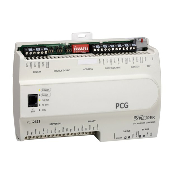
Page 5: Fx-Pcg2621 Physical Features
Cover Life Tab - Removing the controller cover for more information. Display Navigation Buttons - (Not available on all FX-PCG models) LCD Display Area - (Not available on all FX-PCG models) FC Bus - Terminal Block FX-PCG26 General Purpose Programmable Controller Installation Instructions... - Page 6 Important: Use copper conductors only. Make all wiring in accordance with local, national, and regional regulations. Important: Electrostatic discharge can damage controller components. Use proper electrostatic discharge precautions during installation, setup, and servicing to avoid damaging the controller. FX-PCG26 General Purpose Programmable Controller Installation Instructions...
- Page 7 Wire the removable FC bus terminal block plugs on the controller, and other controllers in a daisy- chain configuration using 3-wire twisted, shielded cable as shown below. See Table 6 for more information. Figure 4: FC bus terminal block wiring FX-PCG26 General Purpose Programmable Controller Installation Instructions...
- Page 8 ® Bus Router. The FC bus port is connected internally to the FC bus terminal block. See Table 6 for more information. The FC bus Port pin assignment is shown in Figure 6. FX-PCG26 General Purpose Programmable Controller Installation Instructions...
- Page 9 Wire the 24 VAC supply power wires from the transformer to the HOT and COM terminals on the terminal plug as shown below. The middle terminal on the supply power terminal block is not used. See Table 6 for more information about the Supply Terminal Block. FX-PCG26 General Purpose Programmable Controller Installation Instructions...
-
Page 10: Wireless Network Applications
Note: In wireless network applications, do not connect any wires to the FC bus terminal block. (Connect the SA/FC terminal block on a PCX to an SA bus only.) Connect the FX-ZFR181x or FX-ZFR182x Wireless Field Bus Router to the FC bus port (RJ-12 FX-PCG26 General Purpose Programmable Controller Installation Instructions... -
Page 11: Termination Details
Wireless Field Bus System Product Bulletin (LIT-12011336). Termination details A set of Johnson Controls termination diagrams provides details for wiring inputs and outputs to the controllers. See the figures in this section for the applicable termination diagrams. Table 2: Termination details... - Page 12 Current Input - External Source (Isolated) Current Input - Internal Source (2-wire) Current Input - Internal Source (3 wire) Current Input - External Source (in Loop) Feedback from EPP-1000 Dry Contact (Binary Input) FX-PCG26 General Purpose Programmable Controller Installation Instructions...
- Page 13 Type of Termination diagrams device Input/ Output 0–10 VDC Output to Actuator (External Source) 0–10 VDC Output to Actuator (Internal Source) 4–20 mA Output to Actuator 4–20 mA Output to Actuator Voltage (Analog Output) FX-PCG26 General Purpose Programmable Controller Installation Instructions...
- Page 14 Source) Incremental Control to Actuator (Switch Low, Externally Sourced) 24 VAC Binary Output (Switch High, Externally Sourced) Incremental Control to Actuator (Switch High, Externally Sourced) Incremental Control to Actuator (Switch Low, Externally Sourced) FX-PCG26 General Purpose Programmable Controller Installation Instructions...
- Page 15 24 VAC Binary Output (Switch Low, Externally Sourced) Incremental Control to Actuator (Switch High, Externally Sourced) 24 VAC Binary Output (Switch High, Externally Sourced) Network Stat with Phone Jack (Fixed Address = 199) FX-PCG26 General Purpose Programmable Controller Installation Instructions...
-
Page 16: Terminal Wiring Guidelines, Functions, Ratings, And Requirements
• Inputs/outputs with cables less than 30 m (100 ft) typically do not require an offset in the software setup. Cable runs over 30 m (100 ft) may require an offset in the input/output software setup. FX-PCG26 General Purpose Programmable Controller Installation Instructions... -
Page 17: Fx-Pcg2511 And Fx-Pcg26 Point Type Counts
FX-PCG2511 and FX-PCG26 point type counts The following table shows the different point types and counts available in the FX-PCG2511 and FX- PCG26 Series controllers. Table 3: FX-PCG2511 and FX-PCG26 point type counts per model Point types Signals accepted FX-PCG2511... - Page 18 Table 4: FX-PCG2511 and FX-PCG26 terminal blocks, functions, ratings, requirements, and cables Terminal block Terminal Function, ratings, Determine wire size and label label requirements maximum cable length UNIVERSAL +15 V 15 VDC Power Source for Same as (Universal) INn active (3-wire) input devices...
- Page 19 Table 4: FX-PCG2511 and FX-PCG26 terminal blocks, functions, ratings, requirements, and cables Terminal block Terminal Function, ratings, Determine wire size and label label requirements maximum cable length ICOMn Universal Input Common for Same as (Universal) INn all Universal Input terminals...
- Page 20 Table 4: FX-PCG2511 and FX-PCG26 terminal blocks, functions, ratings, requirements, and cables Terminal block Terminal Function, ratings, Determine wire size and label label requirements maximum cable length ANALOG OUTn Analog Output - Voltage See Guideline C in Table 5. Mode (0–10 VDC)
- Page 21 Table 4: FX-PCG2511 and FX-PCG26 terminal blocks, functions, ratings, requirements, and cables Terminal block Terminal Function, ratings, Determine wire size and label label requirements maximum cable length BINARY OUTn Binary Output - 24 VAC Triac See Guideline C in Table 5.
- Page 22 Table 4: FX-PCG2511 and FX-PCG26 terminal blocks, functions, ratings, requirements, and cables Terminal block Terminal Function, ratings, Determine wire size and label label requirements maximum cable length CONFIGURABLE OUTn Analog Output - Voltage See Guideline A in Table 5. Mode (0–10 VDC)
-
Page 23: Cable Length Guidelines For Recommended Wire Sizes Table
Use Figure 8 to estimate the maximum cable length relative to the wire size and the load current (in mA) when wiring inputs and outputs. Note: Figure 8 applies to low-voltage (<30 V) inputs and outputs only. FX-PCG26 General Purpose Programmable Controller Installation Instructions... -
Page 24: Max Wire Length By Current And Wire Size Graphic
Note: The SA Bus and FC Bus wiring recommendations in this table are for MS/TP bus communications at 38.4k baud. For more information, refer to the FX-PC Series Controllers MS/ TP Communications Bus Technical Bulletin (LIT-12011670) or MS/TP Communications Bus for BCPro System Technical Bulletin (LIT-12011908). FX-PCG26 General Purpose Programmable Controller Installation Instructions... - Page 25 24 VAC Power Supply - Hot 0.8 mm to 1.0 mm Supplies 20–30 VAC (Nominal 24 VAC) (18 AWG) 2-wire 24 VAC Power Supply Common (Isolated from all other Common terminals on controller) 35 VA FX-PCG26 General Purpose Programmable Controller Installation Instructions...
-
Page 26: Setup And Adjustments
Note: Refer to the FX-ZFR Series Wireless Field Bus System Technical Bulletin (LIT-12011660) for more information on device addresses in wireless applications. Set a unique and sequential device address for each of the controllers connected on the SA or FC bus starting with device address 4. FX-PCG26 General Purpose Programmable Controller Installation Instructions... -
Page 27: Removing The Controller Cover
Write each FX-PCG's device address on the white label below the DIP switch block on the controller's cover. Table 7 describes the FC bus and SA bus devices addresses for Johnson Controls MS/TP com- munications bus applications. Refer to the FX-PC Series Controllers MS/TP Communications Bus Technical Bulletin (LIT-12011670) or MS/TP Communications Bus for BCPro System Technical Bulletin (LIT-12011908) for more information on controller device addresses and how to set them on MS/TP buses. -
Page 28: Setting The End-Of-Line (Eol) Switch
FX-PCG26 cover removed EOL switch & current jumpers Figure 10: FX-PCG26 with cover removed showing EOL switch and jumper positions Setting the End-of-Line (EOL) switch Each controller has an EOL switch, which, when set to ON, sets the controller as a terminating device on the bus. -
Page 29: Setting The Input And Output Jumpers
Figure 12 shows an example of a controller BOs and the associated power selection jumpers to the right of the BOs terminal block. Figure 12: Example binary outputs and the associated source power jumper positions FX-PCG26 General Purpose Programmable Controller Installation Instructions... -
Page 30: Setting Up An Integral Or Local Display
4-20 mA analog inputs. FX-PCG26 current loop jumper ID table Table 8 identifies the current loop jumpers associated with each UI on the FX-PCG26. Table 8: FX-PCG26 UI Inputs and jumper labels Universal Input label... -
Page 31: Troubleshooting Fx-Pcg Controllers
Off Steady = EOL switch in Off position terminating devices) Repair information If a controller fails to operate within its specifications, replace the controller. For a replacement controller, contact your Johnson Controls representative. FX-PCG26 General Purpose Programmable Controller Installation Instructions... -
Page 32: Technical Specifications
FX-PCG2621-0: General Purpose Programmable Controller with Display and Push Button User Interface Supply Voltage 24 VAC (nominal, 20 VAC minimum/30 VAC maximum), 50/60 Hz, power supply Class 2 (North America), Safety Extra-Low Voltage (SELV) (Europe) FX-PCG26 General Purpose Programmable Controller Installation Instructions... - Page 33 Output: 16-bit resolution, +/- 200 mV accuracy in 0-10 VDC applications Terminations Input/Output: Fixed Screw Terminal Blocks SA/FC Bus and Supply Power: 4-Wire and 3-Wire Pluggable Screw Terminal Blocks SA Bus Port: RJ-12 6-Pin Modular Jacks FX-PCG26 General Purpose Programmable Controller Installation Instructions...
-
Page 34: Points Of Single Contact
NO. 32 CHANGJIJANG RD NEW DISTRICT 45143 ESSEN MILWAUKEE WI 53202 WUXI JIANGSU PROVINCE 214028 GERMANY CHINA © 2019 Johnson Controls. All rights reserved. All specifications and other information shown were current as of document revision and are subject to change without notice. www.johnsoncontrols.com...
Need help?
Do you have a question about the FX-PCG26 and is the answer not in the manual?
Questions and answers