Table of Contents
Advertisement
Application
The Facility Explorer SNC Series (F4-SNC) are Ethernet-
based, supervisory controllers that connect Building
Automation System (BAS) networks to IP networks.
The SNC features onboard inputs and outputs for
direct control of equipment. This device monitors and
controls networks of field-level building automation
devices, including HVAC equipment, lighting, security,
and fire safety equipment. The SNC has FIPS 140-2 Level
1 Compliance, which is a United States government
cybersecurity standard that approves cyroptographic
modules/algorithms used for encryption.
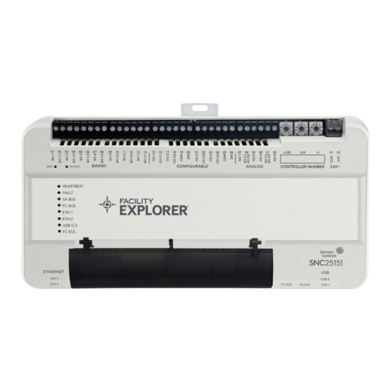
The F4-SNC2515x-0x/x models have a total of 40 I/O points
- with 25 inputs and 15 outputs. The F4-SNC1612x-0x/x
models have a total of 28 I/O points - with 16 inputs and
12 outputs. The first two numbers of the product code
number represent the number of inputs (SNC2515x-0x/
x) and the next two numbers represent the number
Figure 1: F4-SNC2515x-0x/x
F4-SNC Installation Guide
of outputs (SNC2515x-0x/x). The SNC offers various
integration options.
Field Bus integrations supported
• BACnet MS/TP
Ethernet integrations supported
• BACnet/IP
• BACnet/SC
SNC physical features
The following figures display the physical features of the
SNC2515x-0x/x and SNC1612x-0x/x with display models.
The accompanying table provides a description of the
physical features and a reference to further information
where relevant.
*241014302031D*
Part No. 24-10143-02031 Rev. D
2022-12-12
(barcode for factory use only)
F4-SNC2515x-0xx, F4-SNC1612x-0xx
Advertisement
Table of Contents

Related Manuals for Johnson Controls SNC Series


Summary of Contents for Johnson Controls SNC Series
- Page 1 Part No. 24-10143-02031 Rev. D 2022-12-12 Application of outputs (SNC2515x-0x/x). The SNC offers various integration options. The Facility Explorer SNC Series (F4-SNC) are Ethernet- Field Bus integrations supported based, supervisory controllers that connect Building Automation System (BAS) networks to IP networks. • BACnet MS/TP The SNC features onboard inputs and outputs for direct control of equipment.
- Page 2 (bottom). USB-2 (bottom port): Any non-wireless, • SNC25152-0x/x One active Ethernet port, Johnson Controls approved USB device can be 100/10 Mbps; 8-pin RJ45 • SNC16122-0x/x connected to the bottom port. connector, labeled ETH-2 Note: There is one micro-USB port that is (bottom).
-
Page 3: Installation
Materials and special tools needed Table 1: Physical features of the SNC2515x-0x/x and SNC1612x-0x/x You can mount the SNC by using the fasteners option or the DIN rail option. Callout Physical features • Fasteners option - Three fasteners appropriate for the Reset button. -
Page 4: Wiring Overview
Dimensions Figure 3: SNC mounting dimensions, in. (mm) Mounting the SNC for wall mount Press the DIN clips back into position to secure the unit on the DIN rail. applications Mounting the SNC in a panel Use the holes in the three mounting clips for wall mount applications. - Page 5 Ethernet port The Ethernet port is an 8-pin RJ45 network port used to Attention connect the SNC to Ethernet IP networks. You can connect the SNC to Ethernet networks at 1000, 100 or 10 Mbps. The maximum allowable cable length is 100 m (328 ft). Risque de dégâts matériels.
- Page 6 • Follow the transformer manufacturer’s instructions and the project installation drawings. Power supply wire colors may be different on transformers not manufactured by Johnson Controls. • Verify that transformer phasing is uniform across the devices. Power network devices with uniform 24 VAC supply power phasing to reduce noise, interference, and ground loop problems.
-
Page 7: Connecting The Power Source
Connecting the power source. Orange wire (24 VAC) Wires from Johnson Controls 24 VAC, Class Power Transformer Connecting input and output terminals The SNC2515x-0x/x supports up to 40 hard-wired onboard I/O points, 25 inputs and 15 outputs. The SNC1612x supports up to 28 hard-wired onboard I/O points, 16 inputs and 12 outputs. -
Page 8: Terminal Functions, Ratings, Requirements, And Wiring Guidelines
Figure 8: SNC inputs Figure 9: SNC outputs Note: The SNC has two sets of 24+ and common terminal block connections amongst the output pins (Label numbers 19, 20 and 25, 26). The 24 V connection (Label numbers 20 and 26) is the same as the 24V~ HOT connection (Label number 02) and the COM connections (Label numbers 19 and 25) are the same as the 24VAC~ COM connection (Label number 01). - Page 9 See Guideline A in Table 7. Internal 12 V, 15k Ohms pull up. Qualified Sensors: 0–2k potentiometer, RTD (1k Nickel [Johnson Controls sensor], 1k Platinum, and A99B Silicon Temperature Sensor) NTC Sensor (10k Type L, 10k JCI Type II, 2.252k Type II).
- Page 10 Table 6: Terminal wiring Terminal block label Terminal labels Function, ratings, and Determine wire size and requirements maximum cable length ANALOG AO-# Analog Output - Voltage Mode See Guideline C in Table 7. (0–10 VDC) (Outputs) 10 VDC maximum output voltage.
- Page 11 Table 6: Terminal wiring Terminal block label Terminal labels Function, ratings, and Determine wire size and requirements maximum cable length CONFIGURABLE CO-# Analog Output - Voltage Mode See Guideline A in Table 7. (0–10 VDC) (Outputs) 10 VDC maximum output voltage.
-
Page 12: Maximum Cable Length Versus Load Current
Table 7: Cable length guidelines for recommended wire sizes Guideline Wire size/gauge and type Maximum cable length and Assumptions type 1.0 mm (18 AWG) stranded copper 457 m (1,500 ft) twisted wire 100 mV maximum voltage drop Depending on the cable length 0.8 mm (20 AWG) stranded copper 297 m (975 ft) twisted wire and the connected input or... -
Page 13: Termination Diagrams
SNC communication bus SA Bus cables. Termination diagrams A set of Johnson Controls termination diagrams provides details for wiring inputs and outputs to the controllers. See the figures in this section for the applicable termination diagrams. Table 9: Termination diagrams... - Page 14 Table 9: Termination diagrams Type of field device Type of input/ Termination diagrams output Voltage Input - Internal Source Voltage Input (self-powered) Current Input - External Source (isolated) Current Input - Internal Source (2-wire) Current Input - Internal Source (3-wire) Current Input - External Source (in loop) F4-SNC Installation Guide...
- Page 15 Table 9: Termination diagrams Type of field device Type of input/ Termination diagrams output Feedback from EPP-1000 Dry Contact (binary input) UI or BI 0–10 VDC Output to Actuator CO or AO (external source) 0–10 VDC Output to Actuator CO or AO (internal source) Current Output Analog Output (current)
- Page 16 Table 9: Termination diagrams Type of field device Type of input/ Termination diagrams output 24 VAC Triac output (switch low, BO or CO external source) Incremental control to actuator (switch high, external source, Triac) Incremental control to actuator (switch low, external source, Triac) Network Stat with Phone Jack SA Bus...
-
Page 17: Setting The Eol Switch
Table 9: Termination diagrams Type of field device Type of input/ Termination diagrams output NS8000 series sensors SA Bus Network Stat with Terminals SA Bus (Fixed Address = 199) Input/Output wiring validation To set a SNC as an FC Bus terminated device, position the switch on the EOL switch to the ON position as shown in The SNC includes integral wiring validation for onboard Figure 11. -
Page 18: Troubleshooting
Disconnecting power from the SNC switches are set to 1 2 3. If you change the controller number, refresh the SMP Hardware tab to see the Disconnect power from the SNC by removing the gray 2- change. pin terminal block from the 24 V~ power terminal port on the SNC. - Page 19 Table 10: SNC LED designations, normal statuses, descriptions, and other conditions LED name Color State Description HEARTBEAT Multi-color: blue Flashing blue 1 blink per second (1 Hz) = Normal operating system and all monitored or purple and purple processes start and the device is running On blue Power is supplied by 24 VAC, but controller is non-operational Medium flicker,...
-
Page 20: Reset Button
Reset button Recovery to same partition The Recovery button must be pressed continuously for The SNC features a recessed Reset button that is located 5-10 seconds. After 5 seconds the fault LED will start directly above the LEDs and to the left of the Recovery blinking once every second, which is the indicator to button. - Page 21 Wiring considerations and guidelines Table 11: Ethernet network rules Category Allowed maximums and rules General Star topology with network switches Line length and type 2,000 m (6,600 ft) for plastic or glass fiber optic with external adapter 1000 BaseT: 100 m (330 ft) CAT5E cable 100 BaseT: 100 m (330 ft) CAT5 cable 10 BaseT: 100 m (330 ft) CAT5 cable Terminations...
- Page 22 SNC capabilities Table 14: SNC capabilities F4-SNC2515x-0 F4-SNC2515x-04 F4-SNC1612x-0 F4-SNC1612x-04 F4-SNC2515x-0H F4-SNC2515x-04H F4-SNC1612x-0H F4-SNC1612x-04H Onboard I/O 25 inputs/15 outputs 25 inputs/15 outputs 16 inputs/12 outputs 16 inputs/12 outputs Maximum 2500 2500 2500 2500 objects in device Number of site devices including self Maximum allowed...
-
Page 23: Accessories Ordering Information
The SNC25152-0x and SNC16122-0x models are both available with integral displays. To order an SNC with an integral display, add H after the product code number. Table 15: SNC base features Product code number Description F4-SNCxxxx-0x/x Supervisory Network Control Series Every SNC model includes the following functionality: •... - Page 24 Table 17: SNC accessories ordering information Product Code Number Description ACC-USBRS232-0 USB to RS232 adapter. Tested and qualified for use with the SNC. TL-CCT-0 License enabling CCT software for one user. TL-SCT-6 System Configuration Tool software for local installations. Upgrade software for previous SCT versions being upgraded to the latest release.
- Page 25 Canada: UL Listed, File E107041, CCN PAZX7, CAN/CSA C22.2 No. 205, Signal Equipment; Industry Canada Compliant, ICES-003 Europe: Johnson Controls declares that this product is in compliance with the essential requirements and other relevant provisions of the EMC Directive. Australia and New Zealand: RCM Mark, Australia/NZ Emissions Compliant...
- Page 26 Canada: UL Listed, File E107041, CCN PAZX7, CAN/CSA C22.2 No. 205, Signal Equipment; Industry Canada Compliant, ICES-003 Europe: Johnson Controls declares that this product is in compliance with the essential requirements and other relevant provisions of the EMC Directive. Australia and New Zealand: RCM Mark, Australia/NZ Emissions Compliant BACnet International: BTL 135-2020 Listed B-BC/B-RTR/B-BBMD, Protocol Revision 18 FIPS 140-2 Level 1: Compliant and certified with Federal Information Processing Standard;...
-
Page 27: Repair Information
The performance specifications are nominal and conform to acceptable industry standard. For application at conditions beyond these specifications, consult the local Johnson Controls office. Johnson Controls shall not be liable for damages resulting from ® misapplication or misuse of its products. - Page 28 © 2022 Johnson Controls. All rights reserved. All specifications and other information shown were current as of document revision and are subject to change without notice. www.johnsoncontrols.com...
Need help?
Do you have a question about the SNC Series and is the answer not in the manual?
Questions and answers