Table of Contents
Advertisement
Applications
This document describes how to mount and wire the following:
• DIN-mount, 24 VAC/DC powered FX80 controller
• Wall-mount, Class 2 universal AC power adapter supplying 24 VAC
Note: The FX80 controller requires, at a minimum, FX Supervisory Release 14.1. A maximum
of four total option card modules are supported. Separate limits may exist in the controller's
license to further limit functionality.
North American Emissions Compliance
United States
This equipment has been tested and found to comply with the limits for a Class A digital device
pursuant to Part 15 of the FCC Rules. These limits are designed to provide reasonable protection
against harmful interference when this equipment is operated in a commercial environment.
This equipment generates, uses, and can radiate radio frequency energy and, if not installed
and used in accordance with the instruction manual, may cause harmful interference to
radio communications. Operation of this equipment in a residential area may cause harmful
interference, in which case the users will be required to correct the interference at their own
expense.
Part No. 24-10143-861 Rev. A
2019-03-22
FX80 Supervisory Controller Installation
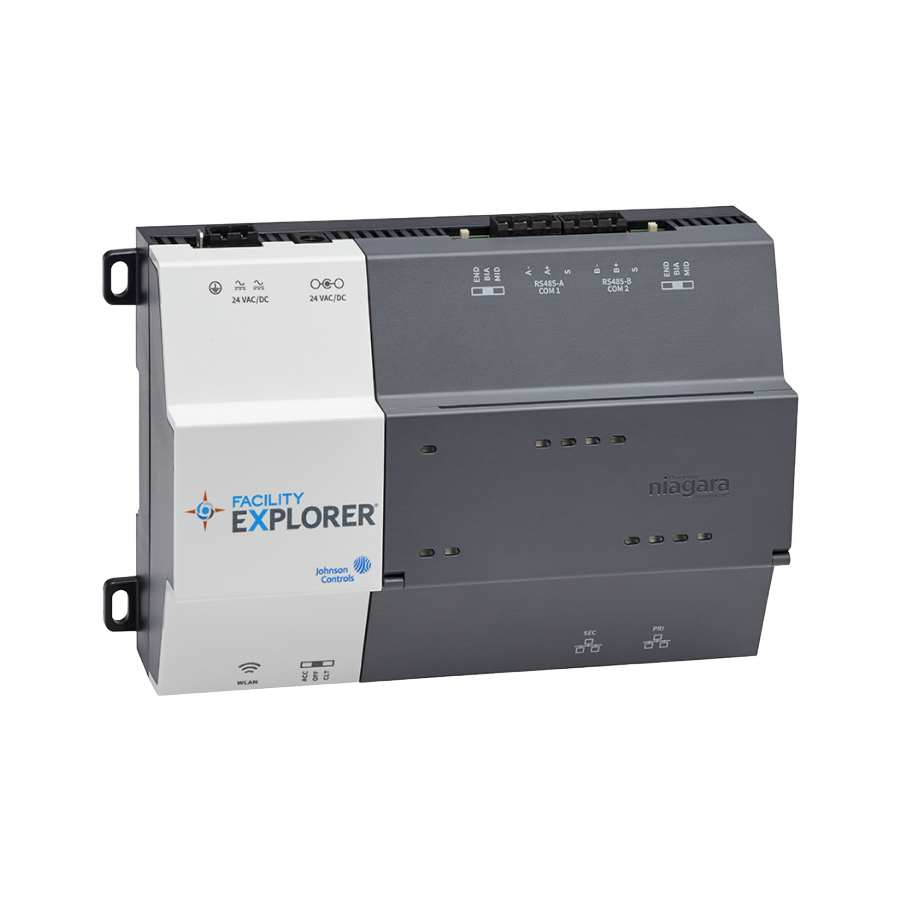
Figure 1: FX80 Controller
Instructions
*2410143861A*
(barcode for factory use only)
FX-SC8BASE-0, FX-SC8BASE-700
Advertisement
Table of Contents

Related Manuals for Johnson Controls FX80


Summary of Contents for Johnson Controls FX80
- Page 1 • Wall-mount, Class 2 universal AC power adapter supplying 24 VAC Note: The FX80 controller requires, at a minimum, FX Supervisory Release 14.1. A maximum of four total option card modules are supported. Separate limits may exist in the controller’s license to further limit functionality.
-
Page 2: Installation
Cet appareil numérique de la Classe (A) respecte toutes les exigences du Règlement sur le matériel brouilleur du Canada. Installation Unpack the FX80 controller and inspect the contents of the package for damaged or missing components. If the controller is damaged, contact the Johnson Controls Product Sales Operations ®... -
Page 3: Physical Mounting
Important: Use copper conductors only. Make all wiring in accordance with local, national, and regional regulations. Do not exceed the FX80 Supervisory Controller’s electrical ratings. Important: Remove all power to controller before attaching (plug in) or detaching (unplug) any option card module, to prevent possible equipment damage. -
Page 4: Environmental Requirements
Note: Horizontal mounting is strongly recommended to achieve maximum heat dissipation and meet the operating temperature upper limit. Any other mounting orientation reduces this upper limit. Mounting on the DIN rail Pull the controller’s locking clip down. FX80 Supervisory Controller Installation Instructions... -
Page 5: Earth Ground And Power
(four maximum). Secure both ends of the final assembly with DIN rail end-clips provided by the DIN rail vendor. Wiring Earth ground and power Earth grounding provides protection from electrostatic discharge or other forms of EMI. FX80 Supervisory Controller Installation Instructions... -
Page 6: Communications Wiring
Unplug the controller's 2-position power connector plug and terminate the 24 V supply source (AC or DC) to the connector. Leave the connector unplugged. Communications wiring FX80 Supervisory Controller Installation Instructions... - Page 7 Use shielded, twisted-pair, 18-22 AWG cabling to wire in a continuous daisy chain fashion to other RS-485 devices: minus-to-minus, plus-to-plus, and shield-to-shield. Connect the shield wire to earth ground at one end only. For more information about wiring guidelines, refer to FX-PC Series Controllers MS/TP Communications Bus Technical Bulletin (LIT-12011670). FX80 Supervisory Controller Installation Instructions...
- Page 8 32 or more devices may be supported depending on device specifications. RS-485 bias switches Each RS-485 port has an adjacent 3-position biasing switch, with these settings: • BIA - (Default, middle) Controller provides RS485 biasing, but without a termination resistor. FX80 Supervisory Controller Installation Instructions...
-
Page 9: Ethernet Wiring
Hz flash at 50/50 percent on/off duty cycle of the BEAT LED returns. LEDs The controller provides a number of status LEDs. All but one of the LEDs are visible with the front access door closed. Figure 8: LEDs and descriptions FX80 Supervisory Controller Installation Instructions... - Page 10 Card carrier inside the controller MicroSD card to insert or remove from the card carrier Important: Disconnect all power to the controller before removing or inserting the microSD card. Otherwise, equipment damage is likely to occur. FX80 Supervisory Controller Installation Instructions...
- Page 11 Use a serial terminal program (for example: PuTTY) to access the controller’s system shell menu. The system shell menu provides access to a few basic platform settings. The default DEBUG port settings are 115200, 8, N, 1 (baud rate, data bits, parity, stop bits). FX80 Supervisory Controller Installation Instructions...
- Page 12 © 2019 Johnson Controls. All rights reserved. All specifications and other information shown were current as of document revision and are subject to change without notice. www.johnsoncontrols.com...
Need help?
Do you have a question about the FX80 and is the answer not in the manual?
Questions and answers