Johnson Controls FEC1611 Installation Instructions Manual
Field equipment controller
Hide thumbs
Also See for FEC1611:
- Installation manual (23 pages) ,
- Installation instructions manual (28 pages)
Table of Contents
Advertisement
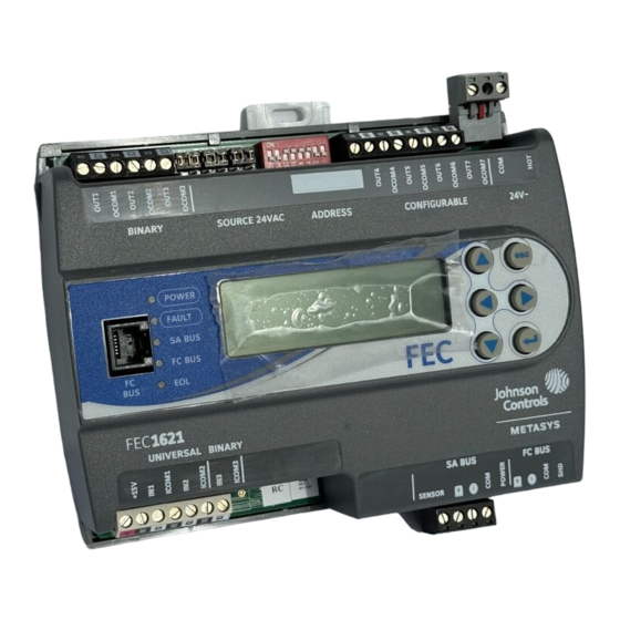
FEC1611 and FEC1621 Field Equipment Controller
Installation Instructions
MS-FEC1611-1, MS-FEC1621-1, MS-FEC1611-1ET
Application
The FEC16 Field Equipment Controller (FEC) is part of the Metasys® system Field Equipment Controller family.
The FEC16 controller runs pre-engineered and user-programmed applications and provides the inputs and outputs
required to monitor and control a wide variety of HVAC equipment.
The FEC controllers can communicate using either BACnet Master-Slave/Token-Passing (MS/TP) or N2
communications protocols. These controllers used as MS/TP devices operate on an RS-485 BACnet® MS/TP Bus
as BACnet Application Specific Controllers (B-ASC) and integrate into Johnson Controls® and third-party BACnet
systems.
The FEC16 controller is available with or without an integral LCD and push-button user interface.
Communications Protocol
The Metasys® system FEC Family Controllers and network sensors communicate using either the standard BACnet
protocol, based on the ANSI/ASHRAE 135-2008, or the BACnet/IP protocol. The BACnet protocol is a standard for
ANSI, ASHRAE, and the International Standards Organization (ISO) for building controls.
FEC, VMA16, VMA18, and most IOM field controllers are BTL-listed as BACnet Application Specific Controllers
(B-ASCs). FAC field controllers and the VMA1930 Field Controller are BTL-listed as BACnet Advanced Application
Controllers (B-AACs).
Release 10.1 and later of the Controller Configuration Tool (CCT) can be used to switch the Field Bus communications
protocol in supported FEC, FAC and VMA controllers to be either the standard BACnet MS/TP or the N2 protocol.
All new controllers use either BACnet MS/TP as the default communications protocol, or BACnet/IP. Switchable
communications protocols in the MS/TP models provide a cost-effective upgrade and modernization path for customers
with existing N2 controllers.
North American Emissions Compliance
Canada
This Class (A) digital apparatus meets all the requirements of the Canadian Interference-Causing Equipment
Regulations.
Cet appareil numérique de la Classe (A) respecte toutes les exigences du Règlement sur le matériel brouilleur du
Canada.
United States
This equipment has been tested and found to comply with the limits for a Class A digital device pursuant to Part
15 of the FCC Rules. These limits are designed to provide reasonable protection against harmful interference when
this equipment is operated in a commercial environment. This equipment generates, uses, and can radiate radio
frequency energy and, if not installed and used in accordance with the instruction manual, may cause harmful
interference to radio communications. Operation of this equipment in a residential area may cause harmful
interference, in which case the users will be required to correct the interference at their own expense.
FEC1611 and FEC1621 Field Equipment Controller Installation Instructions
(barcode for factory use only)
Part No. 24-10143-136, Rev. M
Refer to the
QuickLIT website
for the most up-to-date version of this document.
Issued April 2018
1
Advertisement
Table of Contents

Subscribe to Our Youtube Channel
Related Manuals for Johnson Controls FEC1611


Summary of Contents for Johnson Controls FEC1611
- Page 1 The FEC controllers can communicate using either BACnet Master-Slave/Token-Passing (MS/TP) or N2 communications protocols. These controllers used as MS/TP devices operate on an RS-485 BACnet® MS/TP Bus as BACnet Application Specific Controllers (B-ASC) and integrate into Johnson Controls® and third-party BACnet systems.
-
Page 2: Installation
Mount the controller so that the enclosure walls do not obstruct cover removal or ventilation through the controller. • Mount the controller so that the power transformer and other devices do not radiate excessive heat to the controller. • Do not install the controller in an airtight enclosure. FEC1611 and FEC1621 Field Equipment Controller Installation Instructions... -
Page 3: Din Rail Mount Applications
4. Hold the controller in place, and insert the screws through the mounting clips and into the holes (or anchors). Carefully tighten all of the screws. Important: Do not overtighten the mounting screws. Overtightening the screws may damage the mounting clips. FEC1611 and FEC1621 Field Equipment Controller Installation Instructions... - Page 4 Figure 2: Back of Controller Showing Extended Mounting Clips, DIN Rail Channel, and Mounting Dimensions, mm (in.) FEC1611 and FEC1621 Field Equipment Controller Installation Instructions...
- Page 5 Binary Inputs (BIs) Terminal Block (see Table Universal Inputs (UIs) Terminal Blocks (see Table LED Status Indicators (see Table Field Controller (FC) Bus Port (RJ-12 6-pin Modular Jack) (see Figure Binary Output (BO) Terminal Block (see Table FEC1611 and FEC1621 Field Equipment Controller Installation Instructions...
-
Page 6: Fec Terminal Blocks And Bus Ports
Wire the removable FC bus terminal block plugs on the controller, and other controllers in a daisy-chain configuration using 3-wire twisted, shielded cable as shown in Figure 4. See Table 5 for more information. FEC1611 and FEC1621 Field Equipment Controller Installation Instructions... -
Page 7: Sa Bus Terminal Block
Figure 5: SA Bus Terminal Block Wiring Note: The SA PWR terminal supplies 15 VDC. The SA PWR terminal can be used to connect (daisy chain) the 15 VDC power leads on the SA bus. FEC1611 and FEC1621 Field Equipment Controller Installation Instructions... -
Page 8: Sensor Port
Wire the 24 VAC supply power wires from the transformer to the HOT and COM terminals on the terminal plug as shown in Figure 7. The middle terminal on the supply power terminal block is not used. See Table 5 for more information about the Supply Terminal Block. FEC1611 and FEC1621 Field Equipment Controller Installation Instructions... -
Page 9: Wireless Field Bus Applications
System Product Bulletin (LIT-12011336). Termination Diagrams A set of Johnson Controls® termination diagrams provides details for wiring inputs and outputs to the controllers. See the figures in this section for the applicable termination diagrams. FEC1611 and FEC1621 Field Equipment Controller Installation Instructions... - Page 10 Type of Termination Diagrams Input/Output Temperature Sensor Voltage Input - External Source Voltage Input - Internal Source Voltage Input (Self-Powered) Current Input - External Source (Isolated) Current Input - Internal Source (2-wire) FEC1611 and FEC1621 Field Equipment Controller Installation Instructions...
- Page 11 Note: Add jumper from 24 VAC Com to only one CO Com (on FEC16xx) or only one AO Com or CO com (on FEC26xx) per transformer. 0–10 VDC Output to CO or AO Actuator (Internal Source) FEC1611 and FEC1621 Field Equipment Controller Installation Instructions...
- Page 12 CO or AO (Switch High, Externally Sourced) Incremental Control to CO or AO Actuator (Switch High, Externally Sourced) 24 VAC Binary Output (Switch Low, Externally Sourced) 24 VAC Binary Output (Switch High, Externally Sourced) FEC1611 and FEC1621 Field Equipment Controller Installation Instructions...
- Page 13 Type of Termination Diagrams Input/Output Incremental Control to Actuator (Switch Low, Externally Sourced) Incremental Control to Actuator (Switch High, Externally Sourced) Network Stat with Phone SA Bus Jack (Fixed Address = 199) FEC1611 and FEC1621 Field Equipment Controller Installation Instructions...
-
Page 14: Terminal Wiring Guidelines, Functions, Ratings, And Requirements
Inputs/outputs with cables less than 30 m (100 ft) typically do not require an offset in the software setup. Cable runs over 30 m (100 ft) may require an offset in the input/output software setup. FEC1611 and FEC1621 Field Equipment Controller Installation Instructions... - Page 15 Binary Input Common for all Binary Input (IN) terminals Note: All Binary ICOMn terminals share a common, which is isolated from all other commons, except the Configurable Output (CO) common (OCOMn) when the CO is defined as an Analog Output. FEC1611 and FEC1621 Field Equipment Controller Installation Instructions...
- Page 16 OUTn Binary Output - 24 VAC Triac (Internal Power Source) See Guideline C in Table (Output) Model FEC1611-0: Sources internal 24 VAC power (24~ COM). Power Selection Jumper positioned to Model FEC1611-1: Sources internal 24 VAC power (24~ Internal (INT) power.
-
Page 17: Cable And Wire Length Guidelines
0.5 mm (24 AWG) stranded copper 61 m (200 ft) twisted wire output point. Figure 8 to select wire size/gauge. Figure 8 to determine Use stranded copper wire cable length. Use twisted wire cable. FEC1611 and FEC1621 Field Equipment Controller Installation Instructions... -
Page 18: Maximum Cable Length Versus Load Current
Shielded cable is strongly recommended for all SA and FC bus cables. • Refer to the MS/TP Communications Bus Technical Bulletin (LIT-12011034) for detailed information about wire size and cable length requirements for the SA and FC buses. FEC1611 and FEC1621 Field Equipment Controller Installation Instructions... -
Page 19: Setup And Adjustments
DIP switch block at the top of the controller (Figure 3). Consult the appropriate Communications Technical Bulletin to find valid addresses for these controllers. FEC1611 and FEC1621 Field Equipment Controller Installation Instructions... - Page 20 5. Write each field controller's device address on the white label below the DIP switch block on the controller's cover. Table 6 describes the FC bus and SA bus devices addresses for Johnson Controls® MS/TP communications bus applications. Refer to the MS/TP Communications Bus Technical Bulletin (LIT-12011034) for more information on controller device addresses and how to set them on MS/TP buses.
-
Page 21: Setting The N2 Controller Address To Be Greater Than 127
After the download is finished, disconnect the 24 VAC supply to the controller. Set the address switch segment labeled 128 to ON. 10. Reattach the FC Bus connector to the controller. 11. Reconnect the 24 VAC supply to the controller. FEC1611 and FEC1621 Field Equipment Controller Installation Instructions... -
Page 22: Removing The Controller Cover
EOL termination rules and EOL switch settings on FC buses. Refer to the N2 Communications Bus Technical Bulletin (LIT-636018) for detailed information about EOL termination rules and EOL switch settings on N2 buses. FEC1611 and FEC1621 Field Equipment Controller Installation Instructions... -
Page 23: Setting The Input And Output Jumpers
10). When a UI is defined (in the system software) as a 4–20 mA Analog Input and the UI’s current loop jumper is in the Disabled (default) position (Figure 13), the 4–20 mA current loop circuit opens whenever power to the controller is interrupted or off. FEC1611 and FEC1621 Field Equipment Controller Installation Instructions... -
Page 24: Setting Up An Integral Or Local Display
FEC1621 models have an integral LCD and push-button user interface that allows you to set up and monitor the FEC, the FEC I/O points, and the modules and I/O points connected on the SA bus. FEC1611 models do not have an integral display, but can be connected to a DIS1710 Local Controller Display. -
Page 25: Repair Information
Off Steady = EOL switch in Off position devices) Repair Information If a controller fails to operate within its specifications, replace the controller. For a replacement controller, contact your Johnson Controls representative. FEC1611 and FEC1621 Field Equipment Controller Installation Instructions... -
Page 26: Technical Specifications
Binary Outputs (BOs) or Configurable Outputs (COs), which can consume up to 12 VA for each BO or CO; for a possible total consumption of an additional 84 VA (maximum). FEC1611 and FEC1621 Field Equipment Controller Installation Instructions... - Page 27 Note: Mounting space requires an additional 50 mm (2 in.) space on top, bottom and front face of controller for easy cover removal, ventilation and wire terminations. Weight 0.4 kg (0.9 lb) FEC1611 and FEC1621 Field Equipment Controller Installation Instructions...
- Page 28 The performance specifications are nominal and conform to acceptable industry standard. For application at conditions beyond these specifications, consult the local Johnson Controls® office. Johnson Controls shall not be liable for damages resulting from misapplication or misuse of its products.
Need help?
Do you have a question about the FEC1611 and is the answer not in the manual?
Questions and answers
FEC 1611 has power supplied to it but the FEC is not working, I have unplugged it to see if it would reset, is there a different way of resetting them?
If the Johnson Controls FEC1611 is not working despite having power, check the FAULT LED status first. If the FAULT LED is on steady, the device may have a fault, no application loaded, or require a main code download if in boot mode. If the POWER LED is off, check for short circuits in the output wiring and cycle power to the controller. To reset the controller, disconnect power, inspect for wiring issues, then restore power. If the issue persists, a main code download may be required.
This answer is automatically generated