Table of Contents
Advertisement
Quick Links
FEC1611 and FEC1621 Field Equipment Controller
Installation Instructions
MS-FEC1611-1U, MS-FEC1621-1U
Application
The FEC16 Field Equipment Controller (FEC) is part of the Metasys® system Field Equipment Controller family.
The FEC16 controller runs pre-engineered and user-programmed applications and provides the inputs and outputs
required to monitor and control a wide variety of HVAC equipment.
The FEC controllers can communicate using either BACnet MS/TP or N2 communications protocols. These controllers
used as MS/TP devices operate on an RS-485 BACnet® MS/TP Bus as BACnet Application Specific Controllers
(B-ASC) and integrate into Johnson Controls® and third-party BACnet systems.
The FEC16 controller is available with or without an integral LCD and push-button user interface.
Important: The MS-FEC1611-1U and MS-FEC1621-1U models are used in Metasys Release 8.1 smoke control
applications and are UL 864 UUKL/UUKLC 10th Edition Smoke Control Listed. You must refer to the
Metasys® System UL 864 10th Edition UUKL/ORD-C100-13 UUKLC Smoke Control System Technical
Bulletin (LIT-12012487) for detailed requirements and procedures for installing, commissioning, and
operating UL 864 UUKL/UUKLC listed Metasys system devices. The UL 864 UUKL/UUKLC listing for
Smoke Control Equipment is voided if (1) you do not use the required software tools at the required
versions; or (2) you do not meet the requirements or do not follow the procedures as documented in
the Metasys® System UL 864 10th Edition UUKL/ORD-C100-13 UUKLC Smoke Control System
Technical Bulletin (LIT-12012487).
Communications Protocol
The Metasys® system FEC Family controllers and network sensors communicate using either the standard BACnet
protocol, based on the ANSI/ASHRAE 135-2004, or the BACnet/IP protocol. The BACnet protocol is a standard for
ANSI, ASHRAE, and the International Standards Organization (ISO) for building controls.
Most FEC, VMA16, VMA18, and IOM field controllers are BTL-listed as BACnet Application Specific Controllers
(B-ASCs). FAC field controllers and the VMA1930 Field Controller are BTL-listed as BACnet Advanced Application
Controllers (B-AACs).
Release 10.3 with Release Module (RM) 10.2 of the Controller Configuration Tool (CCT) can be used to switch the
Field Bus communications protocol in supported FEC, FAC and VMA controllers to be either the standard BACnet
MSTP or the N2 protocol. All new controllers use BACnet MSTP as the default communications protocol. Switchable
communications protocols in the MSTP models provide a cost-effective upgrade and modernization path for customers
with existing N2 controllers.
The N2-capable FEC Family Controllers can be used as functional replacements for legacy N2 controllers. The
N2-capable FEC Family Controllers:
•
have the input and output (I/O) quantities and characteristics of the FEC Family Controllers
•
must be programmed with CCT, which has similar, but not identical programming capabilities as HVACPro,
GX9100, GPL, and other legacy tools
•
support SA Bus devices
•
are available in Buy American versions (most models)
•
are listed for UL864 UUKL/UUKLC (some models). N2 is supported as part of the Metasys® 10th Edition listing
for Smoke Control System Equipment. For details, refer to the Metasys System UL 864 10th Edition
UUKL/ORD-C100-13 UUKLC Smoke Control System Technical Bulletin (LIT-12012487).
FEC1611 and FEC1621 Field Equipment Controller Installation Instructions
Part No. 24-10143-497, Rev. A
Software Release 8.1
Issued March 2018
1
Advertisement
Table of Contents

Related Manuals for Johnson Controls MS-FEC1611-1U


Summary of Contents for Johnson Controls MS-FEC1611-1U
- Page 1 The FEC16 controller is available with or without an integral LCD and push-button user interface. Important: The MS-FEC1611-1U and MS-FEC1621-1U models are used in Metasys Release 8.1 smoke control applications and are UL 864 UUKL/UUKLC 10th Edition Smoke Control Listed. You must refer to the Metasys®...
-
Page 2: North American Emissions Compliance
The N2-capable FEC family controllers: • do not support Zone Bus (for example, TMZ sensors and M100 actuators) or XT-Bus (System 91) devices (for example, XT, XTM, and XP modules) • do not support a wireless connection to the N2 bus •... -
Page 3: Din Rail Mount Applications
• Mount the controller in an area free of corrosive vapors and observe the Ambient Conditions requirements in Table • Provide for sufficient space around the controller for cable and wire connections for easy cover removal and good ventilation through the controller (50 mm [2 in.] minimum on the top, bottom, and front of the controller). •... - Page 4 4. Hold the controller in place, and insert the screws through the mounting clips and into the holes (or anchors). Carefully tighten all of the screws. Important: Do not overtighten the mounting screws. Overtightening the screws may damage the mounting clips.
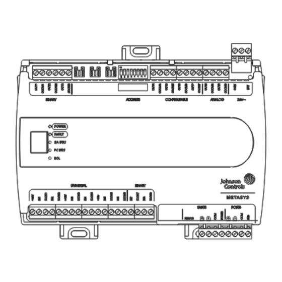
- Page 5 Figure 3: FEC16 Physical Features (FEC1621 Shown) Table 1: FEC16 Physical Features Callouts and Descriptions Callout Physical Feature: Description and References Binary Output (BO) Source Power Selection Jumpers (see Binary Output (BO) Source Power Selection Jumpers) Device Address DIP Switch Block (see Figure Mounting Clip Configurable Output (CO) Terminal Blocks (see...
-
Page 6: Fec Terminal Blocks And Bus Ports
Wiring Risk of Electric Shock: Disconnect the power supply before making electrical connections to avoid electric shock. Mise En Garde: Risque de décharge électrique: Débrancher l'alimentation avant de réaliser tout raccordement électrique afin d'éviter tout risque de décharge électrique. Risk of Property Damage: Do not apply power to the system before checking all wiring connections. Short circuited or improperly connected wires may result in permanent damage to the equipment. -
Page 7: Sa Bus Terminal Block
Figure 4: FC Bus Terminal Block Wiring Note: The FC bus Shield (SHLD) terminal is isolated and can be used to connect (daisy chain) the shields for FC bus wiring. SA Bus Terminal Block The SA Bus terminal block is a brown, removable, 4-terminal plug that fits into a board-mounted jack. Wire the removable SA Bus terminal block plugs on the controller and other SA Bus devices in a daisy-chain configuration using 4-wire twisted, shielded cable as shown in Figure... -
Page 8: Sensor Port
Figure 6: Pin Number Assignments for Sensor, SA Bus, and FC Bus Ports on Controllers Sensor Port The Sensor (SA Bus) port on the bottom of the controller (Figure 3) is an RJ-12, 6-position modular jack that provides a connection for the VAV box Balancing Tool, specified network sensors, or other SA Bus devices with RJ-12 plugs. When the FEC is configured for N2 communication, the SA Bus port must be used to download and commission the controller. -
Page 9: Wireless Field Bus Applications
UUKL/UUKLC Listed Metasys system devices. Termination Diagrams A set of Johnson Controls® termination diagrams provides details for wiring inputs and outputs to the controllers. See the figures in this section for the applicable termination diagrams. FEC1611 and FEC1621 Field Equipment Controller Installation Instructions... - Page 10 Table 2: Termination Details Type of Field Device Type of Termination Diagrams Input/Output Temperature Sensor Voltage Input - External Source Voltage Input - Internal Source Voltage Input (Self-Powered) Current Input - External Source (Isolated) Current Input - Internal Source (2-wire) FEC1611 and FEC1621 Field Equipment Controller Installation Instructions...
- Page 11 Table 2: Termination Details Type of Field Device Type of Termination Diagrams Input/Output Current Input - Internal Source (3 wire) Current Input - External Source (in Loop) Feedback from EPP-1000 Dry Contact (Binary Input) UI or BI 0–10 VDC Output to CO or AO Actuator (External Source) Note: Add jumper from 24 VAC Com to only one CO Com (on FEC16xx) or only...
- Page 12 Table 2: Termination Details Type of Field Device Type of Termination Diagrams Input/Output 24 VAC Triac Output CO or AO (Switch Low, External Source) Incremental Control to CO or AO Actuator (Switch Low, Externally Sourced) 24 VAC Binary Output CO or AO (Switch High, Externally Sourced) Incremental Control to...
- Page 13 Table 2: Termination Details Type of Field Device Type of Termination Diagrams Input/Output Incremental Control to Actuator (Switch Low, Externally Sourced) Incremental Control to Actuator (Switch High, Externally Sourced) Network Stat with Phone SA Bus Jack (Fixed Address = 199) FEC1611 and FEC1621 Field Equipment Controller Installation Instructions...
-
Page 14: Terminal Wiring Guidelines, Functions, Ratings, And Requirements
Table 2: Termination Details Type of Field Device Type of Termination Diagrams Input/Output Network Stat with SA Bus Terminals Addressable Network Stat with SA Bus Terminals (Fixed Address = 199) Terminal Wiring Guidelines, Functions, Ratings, and Requirements Input and Output Wiring Guidelines Table 3 provides information and guidelines about the functions, ratings, and requirements for the controller input and output terminals;... - Page 15 Table Internal 12 V, 15k ohm pull up Qualified Sensors: 0-2k ohm potentiometer, RTD (1k Nickel [Johnson Controls® sensor], 1k Platinum, and A99B Silicon Temperature Sensor) Negative Temperature Coefficient (NTC) Sensor (10k Type L, 10k JCI Type II, 2.252k Type...
- Page 16 Table 3: FEC16 Terminal Blocks, Functions, Ratings, Requirements, and Cables Terminal Block Terminal Function, Ratings, Requirements Determine Wire Size and Label Label Maximum Cable Length BINARY OUTn Binary Output - 24 VAC Triac (External Power Source) See Guideline C in Table (Output) Connects OUTn to OCOMn when activated.
-
Page 17: Cable And Wire Length Guidelines
Table 3: FEC16 Terminal Blocks, Functions, Ratings, Requirements, and Cables Terminal Block Terminal Function, Ratings, Requirements Determine Wire Size and Label Label Maximum Cable Length CONFIGURABLE OUTn Analog Output - Voltage Mode (0–10 VDC) See Guideline A in Table (Outputs) 10 VDC maximum output voltage 10 mA maximum output current Required an external load of 1,000 ohm or more. -
Page 18: Maximum Cable Length Versus Load Current
Maximum Cable Length versus Load Current Figure 8 to estimate the maximum cable length relative to the wire size and the load current (in mA) when wiring inputs and outputs. Note: Figure 8 applies to low-voltage (<30 V) inputs and outputs only. Figure 8: Maximum Wire Length for Low-Voltage (<30 V) Inputs and Outputs by Current and Wire Size SA/FC Bus and Supply Power Wiring Guidelines Table 5... -
Page 19: Setup And Adjustments
Table 5: Communications Bus and Supply Power Terminal Blocks, Functions, Ratings, Requirements, and Cables Terminal Terminal Function, Electrical Ratings/Requirements Recommended Cable Type Block/Port Labels Label FC Bus Communications 0.6 mm (22 AWG) stranded, 3-wire FC BUS twisted, shielded cable recommended Signal Reference (Common) for Bus communications SHLD Isolated terminal (optional shield drain connection) - Page 20 5. Write each field controller's device address on the white label below the DIP switch block on the controller's cover. Table 6 describes the FC bus and SA bus devices addresses for Johnson Controls® MS/TP communications bus applications. Refer to the MS/TP Communications Bus Technical Bulletin (LIT-12011034) for more information on controller device addresses and how to set them on MS/TP buses.
-
Page 21: Setting The N2 Controller Address To Be Greater Than 127
Table 6: SA/FC Bus Device Address Descriptions for MS/TP Controllers Device Address Use on Description 0 to 3 Reserved addresses for wired slave devices (not for use on field controllers). (Switch 128 ON) Note: Metasys field controllers ship with switch 128 ON and the remaining address switches off rendering the controllers wired slave devices, which do not operate on MS/TP buses. -
Page 22: Removing The Controller Cover
Removing the Controller Cover Important: Electrostatic discharge can damage controller components. Use proper electrostatic discharge precautions during installation, setup, and servicing to avoid damaging the controller. Important: Disconnect all power sources to the controller before removing the cover and changing the position of any jumper or the EOL switch on the controller. -
Page 23: Setting The Input And Output Jumpers
3. If the controller is a terminating device on the bus, set the EOL switch to ON. If the controller is not a terminating device on the bus, set the EOL switch to Off. When a field controller is connected to power with its EOL switch set to ON, the amber EOL LED on the controller cover is lit. -
Page 24: Troubleshooting Controllers
Figure 13: Current Loop Jumper Positions Setting the current loop jumper to the Enabled position (Figure 13) connects an internal 100 ohm resistor across the UI terminals, which maintains the 4–20 mA current loop circuit even when power to the controller is interrupted or off. -
Page 25: Repair Information
Repair Information The MS-FEC1611-1U and MS-FEC1621-1U models are UL 864 10th Edition UUKL/ORD-C100-13 UUKLC listed for smoke control. If a controller fails to operate within its specifications, contact the Johnson Controls Repair Center in Louisville, Kentucky, at 1-502-671-7312. Accessories Table 9 for controller accessories ordering information. -
Page 26: Technical Specifications
Technical Specifications Table 10: FEC16 Technical Specifications Product Code Numbers MS-FEC1611-1U: 10-Point FEC MS-FEC1621-1U: 10-Point FEC with integral display and pushbutton user interface. Supply Voltage 24 VAC (nominal, 20 VAC minimum/30 VAC maximum), 50/60 Hz, power supply Class 2 (North America) - Page 27 The performance specifications are nominal and conform to acceptable industry standard. For application at conditions beyond these specifications, consult the local Johnson Controls® office. Johnson Controls shall not be liable for damages resulting from misapplication or misuse of its products.
Need help?
Do you have a question about the MS-FEC1611-1U and is the answer not in the manual?
Questions and answers