Table of Contents
Advertisement
UM2411
User manual
Discovery kit with STM32H747XI MCU
Introduction
The STM32H747I-DISCO Discovery kit is a complete demonstration and development
®
®
platform for the STMicroelectronics Arm
Cortex
-M7 and -M4 dual-core-based
2
2
STM32H747XIH6 microcontroller with four I
C, six SPIs with two multiplexed full-duplex I
S
interfaces, SDIO3.0, SDIO2.0, four USARTs, four UARTs, two FD-CANs, three 16-bit ADCs,
two 12-bit DACs, four SAIs, USB HS OTG and USB FS OTG, Ethernet MAC, FMC interface,
SM
MIPI DSI
host controller, Quad-SPI interface, and JTAG and ETM debugging support.
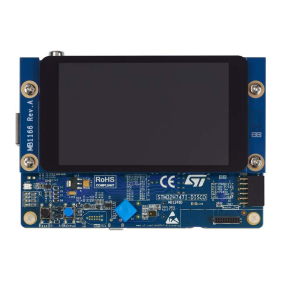
The STM32H747I-DISCO Discovery kit, shown in
Figure 1
and
Figure
2, is used as a
reference design for user application development before porting to the final product.
STM32H747I-DISC1, presented in
Figure
3, is the subset of STM32H747I-DISCO without
the LCD display module.
The full range of hardware features available on the board helps users improve application
development by an evaluation of all the peripherals (USB OTG2 HS, Ethernet, microSD™
card, SAI Audio DAC stereo with audio jack input and output, MEMS digital microphone,
SM
SDRAM, Quad-SPI Flash, DCMI connector, MIPI DSI
interface, and others). Arduino™
Uno V3 and Pmod™/STMod+ connectors provide easy connection to extension shields or
daughterboards for specific applications.
An STLINK-V3E is integrated into the board, as the embedded in-circuit debugger and
programmer for the STM32 MCU and the USB Virtual COM port bridge.
Figure 1. STM32H747I-DISCO top view
Figure 2. STM32H747I-DISCO bottom view
Figure 3. STM32H747I-DISC1 top view
Pictures are not contractual.
PCB colors may differ.
March 2019
UM2411 Rev 2
1/61
www.st.com
1
Advertisement
Table of Contents

Related Manuals for ST STM32H747I-DISCO


Summary of Contents for ST STM32H747I-DISCO
- Page 1 UM2411 User manual Discovery kit with STM32H747XI MCU Introduction The STM32H747I-DISCO Discovery kit is a complete demonstration and development ® ® platform for the STMicroelectronics Arm Cortex -M7 and -M4 dual-core-based STM32H747XIH6 microcontroller with four I C, six SPIs with two multiplexed full-duplex I interfaces, SDIO3.0, SDIO2.0, four USARTs, four UARTs, two FD-CANs, three 16-bit ADCs,...
-
Page 2: Table Of Contents
5.6.2 STM32H747I-DISCO as USB host ......20 Ethernet ..........20 SDRAM . - Page 3 Schematic diagrams ........35 Appendix A STM32H747I-DISCO I/O assignment ......51 Appendix B STMod+ GPIO sharing and multiplexing .
- Page 4 STM32H747I-DISCO I/O assignment ........
- Page 5 STM32H747I-DISCO board layout (top view)........11...
-
Page 6: Features
2 Mbytes of Flash memory and 1 Mbyte of RAM in TFBGA240 + 25 package • 4” capacitive touch LCD display module with MIPI DSI interface (STM32H747I-DISCO order code only) • Ethernet compliant with IEEE802.3-2002 • USB OTG HS •... -
Page 7: Ordering Information
• on the targeted STM32 that is soldered on the board (for illustration of STM32 marking, refer to the section Package information in the STM32 datasheet at www.st.com). • next to the evaluation tool ordering part number, that is stuck or silkscreen printed on... -
Page 8: Codification
MCU, is preloaded in the STM32 Flash memory for easy demonstration of the device peripherals in standalone mode. The latest versions of the demonstration source code and associated documentation can be downloaded from the STM32H747I-DISCO page in the www.st.com... -
Page 9: Delivery Recommendations
In particular, pay attention to the following component: • display MB1166 daughterboard in the CN15 connector if requested For product information related to the STM32H747XIH6 microcontroller, visit the www.st.com website. UM2411 Rev 2 9/61... -
Page 10: Hardware Layout And Configuration
Hardware layout and configuration UM2411 Hardware layout and configuration The STM32H747I-DISCO Discovery kit is designed around the STM32H747XIH6 target microcontroller in TFBGA 240+25-pin package. Figure 4 illustrates the connections of the STM32H747XIH6 with the peripheral components. Figure 5 Figure 6 show the locations of the main components on the Discovery kit. -
Page 11: Figure 5. Stm32H747I-Disco Board Layout (Top View)
UM2411 Hardware layout and configuration Figure 5. STM32H747I-DISCO board layout (top view) UM2411 Rev 2 11/61... -
Page 12: Figure 6. Stm32H747I-Disco Board Layout (Bottom View)
Hardware layout and configuration UM2411 Figure 6. STM32H747I-DISCO board layout (bottom view) 12/61 UM2411 Rev 2... -
Page 13: Figure 7. Stm32H747I-Disco Board Mechanical Dimensions (Top View)
UM2411 Hardware layout and configuration Figure 7 provides the mechanical dimensions of the STM32H747I-DISCO Discovery board. Figure 7. STM32H747I-DISCO board mechanical dimensions (top view) 88mm 77.84mm 5.08mm 37.7mm 16.81mm 48.26mm UM2411 Rev 2 13/61... -
Page 14: Stlink-V3E
Overview of ST-LINK derivatives technical note (TN1235) for details. Power supply The STM32H747I-DISCO discovery kit is designed to be powered from a 5 V DC power source. One of the following five 5 V DC power inputs can be used, upon appropriate board configuration: •... -
Page 15: Supplying The Board Through Stlink-V3E Usb Port
5.2.1 Supplying the board through STLINK-V3E USB port To power the STM32H747I-DISCO in this way, the USB host (a PC) gets connected to the Micro-B USB receptacle of the STM32H747I-DISCO via a USB cable. The connection event starts the USB enumeration procedure. In its initial phase, the host USB port current supply capability is limited to 100 mA. -
Page 16: Smps/Ldo Power Supply
This causes an operating failure of STM32H747I-DISCO. The host PC is not capable of supplying 300 mA (the enumeration fails). The STLINK- V3E does not supply the rest of the STM32H747I-DISCO from its USB port VBUS line. 5.2.3 SMPS/LDO power supply There are two possible solutions to provide power to MCU Vcore: SMPS or LDO. -
Page 17: Table 3. Power-Supply Related Jumper And Solder Bridge Settings
UM2411 Hardware layout and configuration Table 3 details jumper and solder bridge settings used for the configuration of the power supply of STM32H747I-DISCO. Table 3. Power-supply related jumper and solder bridge settings Jumper / Solder bridge Setting Configuration Default setting. -
Page 18: Clock References
The main clock can also be generated using an internal RC oscillator. The X2 reference clock must be disconnected by removing resistor R73 when the internal RC clock is used. Reset Source The general reset of the STM32H747I-DISCO board is active low. The reset sources are: • Reset button B1 •... -
Page 19: Digital Microphone
Micro-AB type. 5.6.1 STM32H747I-DISCO as USB device The STM32H747I-DISCO board may work as USB device on CN1 in any power source configuration. If the board is supplied by an external power source from jumper JP4 set on UM2411 Rev 2... -
Page 20: Stm32H747I-Disco As Usb Host
When a USB device connection to the CN1 Micro-AB USB connector is detected, the STM32H747I-DISCO board starts behaving as USB host. It sources 5 V on the VBUS terminal of CN1 Micro-AB USB connector to power the USB device. For this to happen, the STM32H747XIH6 MCU sets the U2 power switch STMPS2151STR to the ON state via USB3320C. -
Page 21: User Leds
Each LED is in light-emitting state for a low level of the corresponding port of the STM32H747XIH6 MCU. 5.12 Physical input devices The STM32H747I-DISCO board provides a number of input devices for physical human control: • Four-way joystick controller with select key (B3) •... -
Page 22: Connectors
Connectors UM2411 Connectors USB OTG HS Micro-AB connector CN1 An USB OTG high speed communication link is available at USB Micro-AB receptacle connector CN1. Micro-AB receptacle enables USB Host and USB Device features. Figure 8. USB OTG HS Micro-AB connector CN1 Table 5. -
Page 23: Stlink-V3E Usb Micro-B Connector Cn2
UM2411 Connectors STLINK-V3E USB Micro-B connector CN2 USB connector CN2 is used to connect the embedded STLINK-V3E to the PC for programming and debugging software. Figure 9. USB Micro-B connector CN2 Table 6. USB Micro-B connector CN2 Pin number Description Pin number Description VBUS (power) -
Page 24: Arduino™ Uno V3 Connectors Cn5, Cn6, Cn8 And Cn9
PD12 I2C4_SCL 1. The +3V3 on ARD connector Pin4 of CN8 is not a power input for STM32H747I-DISCO board, to simplify power architecture. 2. The external voltage applied to pin VIN on Pin8 of CN8 must be in the range 6 to 9V at 25°C ambient temperature. If a higher voltage is applied on the regulator U19, it may overheat and could be damaged. -
Page 25: Ethernet Rj45 Connector Cn7
A, yellow LED K, green LED A, green LED Audio blue jack (Line In) connector CN10 The 3.5 mm stereo audio blue jack input CN10 is available on the STM32H747I-DISCO Discovery board for audio line input. UM2411 Rev 2 25/61... -
Page 26: Audio Green Jack (Line Out) Connector Cn11
Connectors UM2411 Audio green jack (Line Out) connector CN11 The 3.5 mm stereo audio green jack output CN11 is available on the STM32H747I-DISCO Discovery board for headphones. Figure 11. Stereo headset with microphone jack CN11 Table 11. Audio jack connector CN11 (on board) -
Page 27: Microsd Card Connector Cn12
UM2411 Connectors microSD card connector CN12 microSD cards with 4 Gbytes or more capacity are inserted in the receptacle CN12. Four data bits of the SDMMC1 interface, CLK and CMD signals of the STM32H747XIH6 are used to communicate with the microSD card at +3V3 only. The card insertion is detected by the PI8 GPIO: when a microSD card is inserted, the logic level is 0, otherwise it is 1. -
Page 28: Stdc14 Connector Cn13
Connectors UM2411 6.10 STDC14 connector CN13 Figure 13. STDC14 debugging connector CN13 (top view) Table 13. STDC14 debugging connector CN13 Terminal Function / MCU port Terminal Description SWDIO/TMS (PA13) SWDCLK/TCK (PA14) SWO/TDO (PB3) TDI (PA15) RESET# VCP_RX (PA10) VCP_TX (PA9) 28/61 UM2411 Rev 2... -
Page 29: External 5 V Usb Micro-B Connector Cn14
DSI LCD connector CN15 (MIPI) The CN15 connector is designed to connect the DSI LCD daughterboard. The MB1166 daughterboard is available to be mounted on the STM32H747I-DISCO board. Table 15 shows the assignment of CN15 and STM32H747XIH6 terminals. Figure 15. DSI LCD display connector CN15... -
Page 30: Table 15. Dsi Lcd Module Connector Cn15
Connectors UM2411 Table 15. DSI LCD module connector CN15 CN15 pin Function Function connection number connection DSI_CK_P DSI_INT DSI_CK_N DSI_D0_P DSI_D0_N DSI_D1_P DSI_D1_N BLVDD (5V) BLVDD (5V) BLGND BLGND SCLK/MCLK 3.3 V LRCLK I2S_DATA PD13 I2C_SDA PD12 I2C_SCL CEC_CLK DSI_TE DSI_BL_CTRL PJ12 DSI_RST... -
Page 31: Tag Connector Cn16
UM2411 Connectors 6.13 TAG connector CN16 The TAG connector footprint CN16 is used to connect STM32H747XIH6 microcontroller for programming or debugging the board. Figure 16. TAG connector CN16 Table 16. TAG connector CN16 Pin number Description Pin number Description SWDIO/TMS (PA13) SWDCLK/TCK (PA14) SWO/TDO (PB3) TDI (PA15) -
Page 32: Camera Module Connector P1
P1. The reference of camera module to be used is STM32F4DIS-CAM. This module must be connected with caution before powering the STM32H747I-DISCO Discovery board. The camera module I²C addresses are 0x61 and 0x60. Camera is usable by default. Care must be taken of GPIO sharing and multiplexing with other functions, in order to program the good configuration. -
Page 33: Stmod+ Connector P2
The standard 20-pin STMod+ connector is available on STM32H747I-DISCO board to increase compatibility with external boards and modules from the Ecosystem of microcontrollers. By default, it is designed to support an ST dedicated Fanout board which allows connecting different modules or board extensions from different manufacturers. -
Page 34: Pmod Connector P3
UM2411 6.17 Pmod connector P3 The standard 12-pin Pmod™ connector is available on the STM32H747I-DISCO Discovery board to support low frequency, low I/O pin count peripheral modules. The Pmod™ interface, which has been implemented on the STM32H747I-DISCO Discovery board, is compatible with the Pmod™... -
Page 35: Schematic Diagrams
UM2411 Schematic diagrams Schematic diagrams This chapter provides design schematics for the STM32H747I-DISCO key features to help users to implement these features in application designs: • Figure 20: Overall schematics for the board on page 36 • Figure 21: STM32H747I-DISCO MCU on page 37 •... - Page 36 Figure 20. Overall schematics for the board U_MCU U_Memory MCU.SchDoc Same length Memory.SchDoc R131 +3V3 I2C4_SCL A[0..15] A[0..15] R130 I2C4_SDA D[0..31] D[0..31] U_Audio 90MHz clock SDCLK SDCLK Audio.SchDoc SDNE1 SDNE1 I2C4_SCL SAI1_SCKA SAI1_SCKA SDNRAS SDNRAS I2C4_SDA SAI1_FSA SAI1_FSA SDNCAS SDNCAS SAI1_SDA SAI1_SDA SDNWE...
- Page 37 Figure 21. STM32H747I-DISCO MCU R182 PMOD#1-CTS R180 RMII_REF_CLK R172 ARD_A0 ETH_MDIO SDIO1_CMD ULPI_D0 DCMI_D5 R195 DCMI_HSYNC PMOD#18-DF-CKOUT DSI_RESET R168 PMOD#13-ADC PMOD#4-RTS FMC_NBL2 R169 ARD_D5 ULPI_CK PMOD#2-TX FMC_NBL3 R176 R187 DCMI_PIXCK PMOD#3-RX QSPI_BK1_NCS R188 RMII_CRS_DV SPDIF_RX0 SAI1_MCLKA R179 CEC_CLK SDCLK uSD_Detect...
- Page 38 Figure 22. Power supply LD1117S50TR VDD_MCU Vout C143 C146 10uF(25V) 10uF LDO mode: SB1, SB12, SB49 mounted, SB2, SB11, SB19, SB46, SB48 removed SMPS mode (default): SB2, SB11, SB19, SB46, SB48 mounted, SB1, SB12, SB49 removed SB14, SB15 are backup VDD_MCU VDD_SDC 5V_USB_STLK...
- Page 39 Figure 23. SDRAM memory device D[0..31] D[0..31] A[0..15] A[0..15] DQ31 DQ30 DQ29 DQ28 DQ27 DQ26 DQ25 DQ24 DQ23 DQ22 DQ21 DQ20 DQ19 DQ18 DQ17 DQ16 SDNWE PG15 SDNCAS CAS# DQ15 PF11 SDNRAS RAS# DQ14 SDNE1 DQ13 SDCKE1 DQ12 SDCLK DQ11 DQ10 FMC_NBL3 DQM3...
- Page 40 Figure 24. Audio codec device +3V3 LDO1VDD AGND Default I2C Address:0011010 +3V3 AVDD1 AGND SPKVDD1 AGND +1V8 SPKVDD2 SPKGND1 AVDD2 SPKGND2 +1V8 CPVDD CPGND +3V3 DCVDD DGND DBVDD HP2GND +1V8 LDO2VDD R105 PD13 I2C4_SDA R103 PD12 +3V3 LDO1ENA SCLK I2C4_SCL R108 [N/A] LDO2ENA...
- Page 41 Figure 25. DSI LCD and camera connector DSI LCD DCMI_D[0..7] DCMI_D[0..7] CN15 Camera Connector DSI_CK_P TOUCH_INT DCMI_D0 DSI_CK_N DSI_D2_P SB29 DCMI_D1 DSI_D2_N SB28 DCMI_D2 DSI_D0_P DCMI_D3 DSI_D0_N DSI_D3_P SB27 DCMI_D4 DSI_D3_N SB26 DCMI_D5 DSI_D1_P DCMI_D6 DSI_D1_N DCMI_D7 BEAD(FCM1608KF-601T03) 10uF 100nF DCMI_PIXCK BEAD(FCM1608KF-601T03) DCMI_HSYNC...
- Page 42 Figure 26. Ethernet +3V3 BEAD(FCM1608KF-601T03) +3V3 I/O1 I/O4 Vbus R167 R161 I/O2 I/O3 C103 USBLC6-4SC6 100nF R170 R164 Diff Pair 100ohm TD_P Diff Pair 100ohm PG11 TD_N RMII_TX_EN TXEN PG13 RMII_TXD0 TXD0 PG12 RD_P RMII_TXD1 TXD1 R171 RD_N RMII_RXD0 RXD0/MODE0 R175 Diff Pair 100ohm RMII_RXD1...
- Page 43 Figure 27. Quad-SPI Flash memory devices Twin Quad SPI Flash QSPI_CLK BK2_IO3 SB25 QSPI_CLK QSPI_BK1_IO3 HOLD#/DQ3 QSPI_CLK HOLD#/DQ3 R135 PD11 BK2_IO0 +3V3 QSPI_BK1_IO0 +3V3 R125 100nF BK2_IO0 QSPI_BK2_IO0 33[N/A] 100nF PG14 BK2_IO3 33[N/A] QSPI_BK2_IO3 BK2_IO1 33[N/A] BK2_IO2 QSPI_BK2_IO1 QSPI_BK2_IO2 33[N/A] SB47 NCS2 NCS2...
- Page 44 Figure 28. Physical control peripherals and microSD™ card Buttons LEDs +3V3 R216 +3V3 Green +3V3 MICRO SD R203 PI12 LED1 (TF) Card R115 R118 R119 R116 R117 Orange R204 C151 USER PI13 LED2 [N/A] SDIO1_D1 SDIO1_D0 R215 R205 PC13 PI14 PC11 WAKEUP LED3...
- Page 45 Figure 29. Pmod, STMod+ and audio connectors PMOD PMOD#1 PMOD#11 PMOD#2 PMOD#12 PMOD#3 PMOD#4 +3V3 SSW-106-02-F-D-RA ATOM FH254206C-1600 STMod+ PA11 SB32 PMOD#1-NSS SB31 PMOD#1 PMOD#1-CTS SB34 PMOD#11 PMOD#2-MOSIp PMOD#11-INT SB33 PMOD#2 PMOD#12 PJ13 PMOD#2-TX PMOD#12-RST SB36 PMOD#3 PMOD#3-MISOp PMOD#13-ADC SB35 PMOD#4 PMOD#14 PMOD#3-RX...
- Page 46 Figure 30. TAG debug connector +3V3 CN16 PA13 R208 TMS/SWDIO PA14 R207 TCK/SWCLK TC2050-IDC-NL Fitted: NO Only footprint with Cable: TC2050-IDC-NL R206 TDO/SWO PA15 R212 R211 TRST R210 RESET# ESDALC6V1W5 ESDALC6V1W5 Title: TAG Connector Project: STM32H7-DK Size: Reference: MB1248 Revision: Date: 1/21/2019 Sheet:...
- Page 47 Figure 31. Arduino™ Uno connector Arduino uno connector +3V3 ARD_D15 I2C4_SCL BSN20BK ARD_D14 I2C4_SDA Green VREF+ [N/A] +3V3 [N/A] PD12 SCL/D15 R120 PD13 SDA/D14 AVDD IOREF SCK/D13 ARD_D13 SPI5_SCK PJ11 NRST NRST NRST MISO/D12 ARD_D12 SPI5_MISO PJ10 PWM/MOSI/D11 ARD_D11 TIM1_CH2N, SPI5_MOSI PWM/CS/D10 ARD_D10 TIM1_CH1, SPI5_NSS...
- Page 48 OSC32_OUT/PC15 MCO/PA8 2.2uF T_NRSTa V12_OTGPHY/PG7 T_NRST/PA5 20pF R100 REXT_OTGPHY/PG6 Fitted: NO HW_TYP_0/PI4 HW_TYP_1/PI5 STDC14 Receiver T_VCC must be to connected to VDD_MCU of the Target ST-LINKV3E_SWD CN13 +3V3 T_VCC T_SWDIO R217 T_SWDIOa T_SWCLK R218 T_SWCLKa T_SWO R219 T_SWOa T_NRST STLK_SWDIO...
- Page 49 Figure 33. STLINK-V3E power 3.3 Volts ST-LINK VBUS_HS 5V_USB_CHGR LDK120M33R 3V3_STLK 5 Volts ST-LINK BAT60JFILM Vout R109 100K BAT60JFILM C144 BYPASS R106 LED Curr=4mA, Lum=25% C145 100nF 5V_USB_PWR C148 C147 5V_USB_STLK BAT60JFILM 100nF C142 10nF 5V_USB_CHGR SB18 BAT60JFILM T_PWR_EN FAULT...
- Page 50 Figure 34. USB_OTG_HS port +3V3 OTG_HS_OverCurrent +3V3 Green FAULT 9013 4.7uF STMPS2151STR ULPI_NXT CPEN PI11 100nF ULPI_DIR VBAT ULPI_STP RBIAS 8K06_1% BLM18PG121SN1D VBUS_HS ULPI_CK CLKOUT VBUS VBUS ULPI_D[0..7] ULPI_D7 ULPI_D[0..7] PB13 ULPI_D6 PB12 ULPI_D5 PB11 ULPI_D4 PB10 ULPI_D3 OSC_24M ULPI_D2 Shield ULPI_D1 REFSEL0...
-
Page 51: Appendix A Stm32H747I-Disco I/O Assignment
UM2411 STM32H747I-DISCO I/O assignment Appendix A STM32H747I-DISCO I/O assignment Table 21. STM32H747I-DISCO I/O assignment GPIO port GPIO primary interface QSPI_BK2_IO2 PMOD#2- USART2_TX PMOD#4- USART2_RTS PC10 SDIO1_D2 PA15 JTDI FMC_D25 FMC_D24 FMC_D28 FMC_NBL3 FMC_NBL2 ULPI_D7 VDDLDO VCAP JOY_RIGHT PG10 DCMI_D2 VBAT... - Page 52 STM32H747I-DISCO I/O assignment UM2411 Table 21. STM32H747I-DISCO I/O assignment (continued) GPIO port GPIO primary interface JOY_LEFT PG11 ETH_/TX_EN/TX_EN PC15-OSC32_OUT OSC32_OUT SPDIF_RX0 PC12 SDIO1_CK FMC_D27 PA13 JTMS-SWDIO VDDLDO PC14-OSC32_IN OSC32_IN ETH_nINT || SAI4_CK1 FMC_NBL0 DCMI_VSYNC JTDO/TRACESWO JOY_UP JOY_DOWN PG12 ETH_/TXD1/TXD1 SAI1_SCK_A...
- Page 53 UM2411 STM32H747I-DISCO I/O assignment Table 21. STM32H747I-DISCO I/O assignment (continued) GPIO port GPIO primary interface PG13 ETH_/TXD0/TXD0 VLXSMPS PJ13 PMOD#12_GPIO FMC_D3 SDIO1_D0 SDIO1_D1 || DCMI_D3 CEC_CK || MCO1 PA12 PMOD#4-SPI2_SCK/2_CK PA11 PMOD#1-SPI2_NSS/2_WS FMC_D30 PC13 TAMP_1/WKUP2 uSD_Detect SAI1_SD_A PDR_ON BOOT0 VDDSMPS...
- Page 54 STM32H747I-DISCO I/O assignment UM2411 Table 21. STM32H747I-DISCO I/O assignment (continued) GPIO port GPIO primary interface VDD50USB VFBSMPS FMC_A1 FMC_A0 PI12 LED1 FMC_BA0 DSI_Reset FMC_A12 JOY_SEL PI13 LED2 PI14 LED3 FMC_A3 PH1 - OSC_OUT OSC_OUT ARD_D13-SPI5_SCK ARD_D10-SPI5_NSS || TIM1_CH1 PH0 - OSC_IN...
- Page 55 UM2411 STM32H747I-DISCO I/O assignment Table 21. STM32H747I-DISCO I/O assignment (continued) GPIO port GPIO primary interface NRST NRST PJ11 ARD_D12-SPI5_MISO VSSDSI DSI_D1P DSI_D1N QSPI_BK1_IO3 QSPI_BK1_IO2 PMOD#14_PWM || ARD_D3-TIM13_CH1 VDDA PJ10 ARD_D11-SPI5_MOSI || TIM1_CH2N VSSDSI DSI_CKP DSI_CKN ULPI_STP PF10 ARD_A1 QSPI_BK1_IO1 VREF+...
- Page 56 STM32H747I-DISCO I/O assignment UM2411 Table 21. STM32H747I-DISCO I/O assignment (continued) GPIO port GPIO primary interface ARD_D0-UART8_RX VSSDSI DSI_D0P DSI_D0N ETH_MDC || SAI4_D1 PMOD#3-SPI2_MISO/2_SDI PMOD#2-SPI2_MOSI/2_SDO VREF- ARD_D1-UART8_TX ARD_D6-TIM8_CH2N ARD_D9-TIM8_CH2 VCAPDSI QSPI_BK2_IO0 ETH_MDIO ETH_/RX_CLK/REF_CLK/CLK PMOD#1- USART2_CTS_NSS ARD_D7 PE10 FMC_D7 VSSA PE11 FMC_D8...
- Page 57 UM2411 STM32H747I-DISCO I/O assignment Table 21. STM32H747I-DISCO I/O assignment (continued) GPIO port GPIO primary interface ULPI_NXT FMC_SDNWE PI15 LED4 OTG_HS_OverCurrent PF13 FMC_A7 PF14 FMC_A8 FMC_D6 PC2_C ARD_A4 PE12 FMC_D9 PE15 FMC_D12 ARD_D8 FMC_D17 PH12 FMC_D20 PD11 QSPI_BK1_IO0 PD12 PMOD#7/ARD_D15-I2C4_SCL PD13...
- Page 58 STM32H747I-DISCO I/O assignment UM2411 Table 21. STM32H747I-DISCO I/O assignment (continued) GPIO port GPIO primary interface ETH_/RXD0/RXD0/RXD ULPI_D2 DSI_TE PF11 FMC_SDNRAS FMC_A10 FMC_D5 PE14 FMC_D11 VCAP1 VDDLDO FMC_SDCKE1 PB13 ULPI_D6 PB14 PMOD#9-SPI2_MISO/2_SDI FMC_D13 ULPI_D0 PMOD#13_ADC || ARD_A0 || DCMI_HSYNC ETH_/RXD1/RXD1 ULPI_D1...
-
Page 59: Appendix B Stmod+ Gpio Sharing And Multiplexing
Appendix B STMod+ GPIO sharing and multiplexing Table 22. STMod+ GPIO sharing and multiplexing Shared or exclusive functions STMod+ Shared or exclusive functions DFSDM Pmod™ Some other Alternate Functions Basic Port Pins Port Basic Some other Alternate Functions Pmod™ DFSDM DCMI CTSS2 ADC123_INO, TIM5_CH1... -
Page 60: Revision History
Revision history UM2411 Revision history Table 23. Document revision history Date Revision Changes 23-Nov-2018 Initial version Updated schematics from Figure 20 Figure 34 Chapter 7: Schematic diagrams. Updated board views Figure Figure 2, and Figure 3 in the cover page. 29-Mar-2019 Reorganized Chapter 2: Ordering information... - Page 61 ST products and/or to this document at any time without notice. Purchasers should obtain the latest relevant information on ST products before placing orders. ST products are sold pursuant to ST’s terms and conditions of sale in place at the time of order acknowledgement.
Need help?
Do you have a question about the STM32H747I-DISCO and is the answer not in the manual?
Questions and answers