ABB i-bus KNX Product Manual
Vc/s 4.x.1 valve drive controller
Hide thumbs
Also See for i-bus KNX:
- Product manual (264 pages) ,
- Product manual (84 pages) ,
- Product manual (152 pages)
Table of Contents
Advertisement
Quick Links
Download this manual
See also:
Product Manual
Advertisement
Table of Contents

Related Manuals for ABB i-bus KNX


Summary of Contents for ABB i-bus KNX
- Page 1 — PRODUCT MANUAL ABB i-bus® KNX VC/S 4.x.1 Valve Drive Controller...
-
Page 3: Table Of Contents
® ABB i-bus Contents Page Contents General ....................5 Using the product manual ......................5 Legal disclaimer ..........................5 Explanation of symbols .........................5 Safety ....................7 General safety instructions ......................7 Proper use ............................7 Product Overview ................9 Product Overview .........................9 Ordering details .......................... 10 Valve drive controller VC/S 4.1.1, MDRC ................... - Page 4 ® ABB i-bus Contents Commissioning .................. 35 Prerequisites for commissioning ....................35 Commissioning overview ......................35 Assignment of the physical address................... 36 Software/application........................37 6.4.1 Download response ........................37 6.4.2 Copying, exchanging and converting ..................37 Parameters ..................38 General ............................38 General parameter window ......................
- Page 5 ® ABB i-bus Contents Setpoint manager parameter window ..................127 7.7.1 Operating modes ........................128 7.7.2 Operating mode after bus voltage recovery, ETS download and reset ........129 7.7.3 Comfort heating setpoint = Comfort cooling setpoint ..............129 7.7.3.1 No ............................. 130 7.7.3.2...
- Page 6 ® ABB i-bus Contents Group objects ................... 196 Summary of group objects VC/S ....................196 Group objects General ......................199 Group objects Channel A – General ..................200 Group objects Channel A – Valve A ..................202 Group objects Channel A – Input a ..................205 Group objects Channel A –...
-
Page 7: General
We reserve the right to make technical changes or modify the contents of this document without prior notice. The agreed properties are definitive for any orders placed. ABB AG does not accept any responsibility whatsoever for potential errors or possible lack of information in this document. - Page 8 ® ABB i-bus General Notes and warnings are represented as follows in this manual: DANGER – This symbol is a warning about electrical voltage and indicates high-risk hazards that will definitely result in death or serious injury unless avoided. DANGER –...
-
Page 9: Safety
® ABB i-bus Safety Safety General safety instructions ► Protect the device from moisture, dirt and damage during transport, storage and operation. ► Operate the device only within the specified technical data. ► Operate the device only in a closed housing (distribution board). -
Page 11: Product Overview
® ABB i-bus Product Overview Product Overview Product Overview The devices are of type modular DIN rail component (MDRC) in Pro M design. The module width of the devices is six space units. They are designed for installation in distribution boards on 35 mm mounting rails. -
Page 12: Ordering Details
® ABB i-bus Product Overview Ordering details Description Type Order No. Unit Packaging Weight price unit 1 pc. [€] [pcs.] Valve Drive Controller VC/S 4.1.1 2CDG110216R0011 Valve Drive Controller VC/S 4.2.1 2CDG110217R0011 Table 4: Ordering details 10 2CDC508220D0211 Rev. A | VC/S 4.x.1... -
Page 13: Valve Drive Controller Vc/S 4.1.1, Mdrc
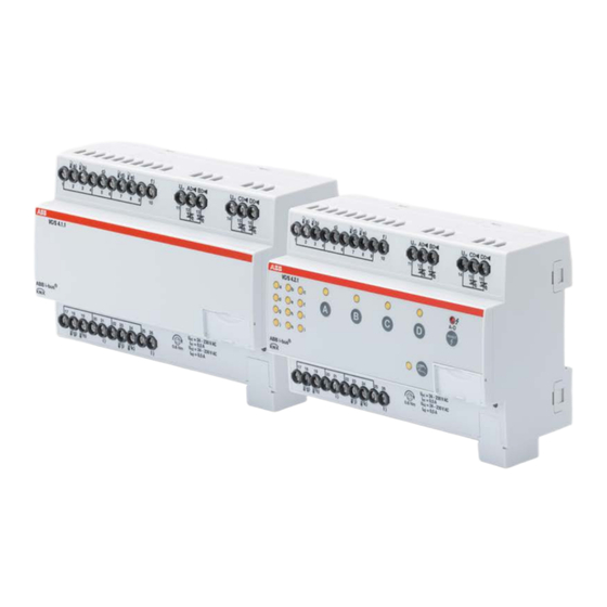
® ABB i-bus Product Overview Valve drive controller VC/S 4.1.1, MDRC Fig. 1: Device illustration VC/S 4.1.1 The device is a modular DIN rail component (MDRC) in pro M design. It is intended for installation in distribution boards on 35 mm mounting rails. Physical address assignment and parametrization are carried out with ETS. -
Page 14: Dimension Drawing
® ABB i-bus Product Overview 3.3.1 Dimension drawing Fig. 2: Dimension drawing 12 2CDC508220D0211 Rev. A | VC/S 4.x.1... -
Page 15: Connection Diagram
® ABB i-bus Product Overview 3.3.2 Connection diagram Fig. 3: Connection diagram VC/S 4.1.1 Legend Label carrier KNX programming LED (red) KNX programming button Bus connection terminal Cover cap Inputs (a, b, c; d, e, f) Inputs (g, h, i; j, k, l) Valve outputs (A, B, C, D) VC/S 4.x.1 | 2CDC508220D0211 Rev. -
Page 16: Operating And Display Elements
® ABB i-bus Product Overview 3.3.3 Operating and display elements Button/LED Description LED indicator Assignment of the physical On: Device is in programming mode address Table 5: Operating and display elements – general 14 2CDC508220D0211 Rev. A | VC/S 4.x.1... -
Page 17: Technical Data
® ABB i-bus Product Overview 3.3.4 Technical data 3.3.4.1 General technical data Power supply Bus voltage 21…32 V DC Current consumption, bus < 12 mA Maximum 250 mW Power loss, bus Power loss, device Maximum 3 W KNX connection 0.25 W Electronic outputs 2.4 W... -
Page 18: Device Type
® ABB i-bus Product Overview 3.3.4.2 Device type Device type Valve Drive Controller VC/S 4.1.1 Application Valve Drive Controller,4-f/…* Maximum number of group objects Maximum number of group addresses Maximum number of assignments * … = Current version number of the application. Please refer to the software information on our homepage for this. -
Page 19: Inputs
® ABB i-bus Product Overview 3.3.4.4 Inputs Rated values Quantity For analog room control unit Quantity 4 (per channel 1) Contact scanning Scanning current 1 mA Scanning voltage 12 V Resistance Select User-defined PT 1.000 2-conductor technology PT 100 2-conductor technology... -
Page 20: Valve Drive Controller Vc/S 4.2.1, Manual Operation, Mdrc
® ABB i-bus Product Overview Valve drive controller VC/S 4.2.1, manual operation, MDRC Fig. 4: Device illustration VC/S 4.2.1 The device is a modular DIN rail component (MDRC) in pro M design. It is intended for installation in distribution boards on 35 mm mounting rails. Physical address assignment and parametrization are carried out with ETS. -
Page 21: Dimension Drawing
® ABB i-bus Product Overview 3.4.1 Dimension drawing Fig. 5: Dimension drawing VC/S 4.x.1 | 2CDC508220D0211 Rev. A 19... -
Page 22: Connection Diagram
® ABB i-bus Product Overview 3.4.2 Connection diagram Fig. 6: Connection diagram VC/S 4.2.1 Legend Label carrier Valve output (A...D) reset/error button/LED KNX programming LED (red) Activate manual operation button/LED KNX programming button Inputs status indicator LEDs (a, b, c, d, e, f, g, h, i, j, k, l) -
Page 23: Operating And Display Elements
® ABB i-bus Product Overview 3.4.3 Operating and display elements Button/LED Description LED indicator Assignment of the physical On: Device is in programming mode address Table 6: Operating and display elements – general 3.4.3.1 Manual operation Button/LED Description LED indicator... -
Page 24: Knx Operation
® ABB i-bus Product Overview 3.4.3.2 KNX operation Button/LED Description LED indicator Button without function On: Valve control value greater than 0 % Off: Valve control value equal to 0 % Flashing: Indicates a fault, Valve output X e.g. overload/short circuit... -
Page 25: Technical Data
® ABB i-bus Product Overview 3.4.4 Technical data 3.4.4.1 General technical data Power supply Bus voltage 21…32 V DC Current consumption, bus < 12 mA Maximum 250 mW Power loss, bus Power loss, device Maximum 3 W KNX connection 0.25 W Electronic outputs 2.4 W... -
Page 26: Device Type
® ABB i-bus Product Overview 3.4.4.2 Device type Device type Valve Drive Controller VC/S 4.2.1 Application Valve Drive Controller, manual operation,4-f/…* Maximum number of group objects Maximum number of group addresses Maximum number of assignments * … = Current version number of the application. Please refer to the software information on our homepage for this. -
Page 27: Inputs
® ABB i-bus Product Overview 3.4.4.4 Inputs Rated values Quantity For analog room control unit Quantity 4 (per channel 1) Contact scanning Scanning current 1 mA Scanning voltage 12 V Resistance Select User-defined PT 1.000 2-conductor technology PT 100 2-conductor technology... -
Page 29: Function
® ABB i-bus Function Function Functional overview Cooling ceilings, floor heating and radiators are used to cool or heat the room. The required room temperature is achieved via these devices using a control. The valve drive controller controls the flow valve and reduces or increases the quantity of hot or cold water to suit the demand for heat/cold in the room. -
Page 30: Input Functions
® ABB i-bus Function Input functions The following table provides an overview of the functions possible with the inputs of the VC/S and the application: Functions Connection of analog room control unit Binary signal input (floating) Temperature sensor PT100 PT1000... -
Page 31: Output Functions
® ABB i-bus Function Output functions 4.3.1 Valve outputs Function Electrothermal Valve Drive (PWM) Solenoid valve (open/close) Error detection Overload Table 11: Valve output function CAUTION – A short circuit will cause irreparable damage to the channel, it will then no longer be possible to use the valve output. -
Page 32: Integration In The I-Bus Tool
Tool. ® You can download the i-bus Tool free of charge from our homepage (www.abb.de/knx). ® A description of the functions is provided in the i-bus Tool online help. 30 2CDC508220D0211 Rev. A | VC/S 4.x.1... -
Page 33: Special Operating States
® ABB i-bus Function Special operating states 4.5.1 Reaction on bus voltage failure/recovery, download and ETS reset The device's reaction on bus voltage failure/recovery, download and ETS reset can be set in the device parameters. CAUTION – If the allocation of the outputs is changed (e.g. Actuate basic-stage heating via from Internal channel output (valve) to Group object) when the device is parametrized, the device resets automatically to ensure the correct function of the outputs. -
Page 35: Mounting And Installation
® ABB i-bus Mounting and installation Mounting and installation Information about mounting The mounting position can be selected as required. The electrical connection is made using screw terminals. The connection to the bus is implemented using the supplied bus connection terminal. The terminal assignment is located on the housing. -
Page 36: Mounting On Din Rail
® ABB i-bus Mounting and installation Mounting on DIN rail The device is fitted and removed without auxiliary tools. Make sure the device is accessible for operation, testing, visual inspection, maintenance and repair. Fig. 7: Mounting on DIN rail Place the DIN rail holder on the upper edge of the DIN rail and push down. -
Page 37: Commissioning
Commissioning Prerequisites for commissioning ® To commission the device, a PC with ETS is required along with a connection to the ABB i-bus e.g. via a KNX interface. The device is ready for operation after the bus voltage is applied. -
Page 38: Assignment Of The Physical Address
® ABB i-bus Commissioning Assignment of the physical address The physical address, group address and parameters are assigned and programmed in ETS. The device features a Programming button for physical address assignment. The red Programming LED lights up after the button has been pressed. It goes off once ETS has assigned the physical address or the Programming button is pressed again. -
Page 39: Software/Application
6.4.2 Copying, exchanging and converting The ABB Update Copy Convert application can be used to copy or exchange parameter settings and to convert the application version. The application is available free of charge from the KNX online shop. It also provides the following functions: •... -
Page 40: Parameters
General ETS Engineering Tool Software is used to parametrize the device. In ETS, the applications are in the Catalogs window under Manufacturers/ABB/Heating, ventilation, air conditioning/ Valve drive controller. The following chapters describe the device parameters based on the parameter windows. Parameter windows are structured dynamically so that further parameters are enabled depending on the parametrization and function of the outputs. -
Page 41: General Parameter Window
® ABB i-bus Parameters General parameter window Fig. 8: General parameter window 7.2.1 Sending and switching delay after bus voltage recovery Options: 2…255 s During the sending and switching delay, telegrams are only received. However, the telegrams are not processed and the outputs remain unchanged. No telegrams are sent on the bus. -
Page 42: State After Sending And Switching Delay Has Elapsed
® ABB i-bus Parameters 7.2.2 State after sending and switching delay has elapsed Options: Last value received Ignore received values • Last value received: During the sending and switching delay, the inputs and outputs continue reading. They send the current value after the delay has elapsed. -
Page 43: Enable Group Object "In Operation", 1 Bit
® ABB i-bus Parameters 7.2.3.2 — Dependent parameter In period Options: 1 second 2 seconds 5 seconds 10 seconds 30 seconds 1 minute This parameter defines the number of telegrams sent by the device within a certain period of time. -
Page 44: Access To I-Bus ® Tool
Deactivated Value display only Full access ® This parameter is used to restrict or forbid completely access by the ABB i-bus Tool. If Deactivated is ® selected, access by the i-bus Tool is completely disabled. If Value display only is selected, no values can ®... -
Page 45: Manual Operation Parameter Window
® ABB i-bus Parameters Manual operation parameter window Fig. 9: Manual operation parameter window 7.3.1 Manual operation Options: Enabled Disabled This parameter defines if the changeover between the operating states Manual operation and KNX operation is possible via the Manual operation button on the device. -
Page 46: Automatically Reset From Manual Operation To Knx Operation
® ABB i-bus Parameters 7.3.2 Automatically reset from manual operation to KNX operation Options: This parameter is only visible if the Enabled option has been selected for the Manual operation parameter. This parameter determines whether, after pressing the Manual operation button, the device will remain in Manual operation or will be reset back to KNX operation. -
Page 47: Application Parameters Parameter Window
® ABB i-bus Parameters Application parameters parameter window The basic settings necessary for the application are made in the Application parameters parameter window. Fig. 10: Application parameters parameter window VC/S 4.x.1 | 2CDC508220D0211 Rev. A 45... -
Page 48: Channel Function
® ABB i-bus Parameters 7.4.1 Channel function Options: Controller channel Actuator channel The function of the channel is set using this parameter. It can be used with the controller activated and optional communication with an analog room control unit, or as a pure actuator channel for controlling a heating or a cooling application (floor heating, radiator heating or cooling ceiling). - Page 49 ® ABB i-bus Parameters 7.4.1.1 — Dependent parameter Basic-stage heating The following description applies in the case that the Controller channel option has been selected in the Channel function parameter. Options: Deactivated Convector (e.g. radiator) Area heating (e.g. floor) Free configuration The type of application for the heating stage is selected with this parameter.
- Page 50 ® ABB i-bus Parameters 7.4.1.1.1 — Dependent parameter Additional-stage heating The following description applies in the case that the Controller channel option has been selected in the Channel function parameter and the Basic-stage heating parameter is not deactivated. Options: Deactivated Convector (e.g.
- Page 51 ® ABB i-bus Parameters 7.4.1.2 — Dependent parameter Basic-stage cooling The following description applies in the case that the Controller channel option has been selected in the Channel function parameter. Options: Deactivated Area cooling (e.g. cooling ceiling) Free configuration The type of application for the basic-stage cooling is selected with this parameter. The controller is pre- configured based on this selection and can be used for the selected application.
- Page 52 ® ABB i-bus Parameters 7.4.1.2.1 — Dependent parameter Additional-stage cooling This parameter is visible if, in the Channel function parameter, the Controller channel option is selected and the Basic-stage cooling parameter is not deactivated. Options: Deactivated Area cooling (e.g. cooling ceiling) Free configuration The type of application for the additional-stage cooling is selected with this parameter.
- Page 53 ® ABB i-bus Parameters 7.4.1.2.2 — Dependent parameter Type of heating/cooling system This parameter is not visible if the Basic-stage heating or Basic-stage cooling parameters are deactivated. Options: 2-pipe 4-pipe This parameter must be selected to suit the heating/cooling system in which the device is to be used.
- Page 54 ® ABB i-bus Parameters 7.4.1.2.3 — Dependent parameter Heating/cooling changeover This parameter is not visible if the Basic-stage heating or Basic-stage cooling parameters are deactivated. Options: Automatically Only via object Via slave and via object The standard value for this parameter depends on the selection in the Type of heating/cooling system parameter.
- Page 55 ® ABB i-bus Parameters 7.4.1.2.4 — Dependent parameter Actuate basic-stage heating via This parameter is not visible if the Basic-stage heating parameter is deactivated. Options: Internal channel output (valve) Group object The way the control value for the basic-stage heating is to be output is set using this parameter.
- Page 56 ® ABB i-bus Parameters 7.4.1.2.5 — Dependent parameter Actuate basic-stage cooling via This parameter is not visible if the Basic-stage cooling parameter is deactivated. Options: Internal channel output (valve) Group object The way the control value for the basic-stage cooling is to be output is set using this parameter.
- Page 57 ® ABB i-bus Parameters 7.4.1.2.6 — Dependent parameter Actuate additional-stage heating via This parameter is not visible if the Additional-stage heating parameter is deactivated. This parameter is not visible if the Actuator channel option has been selected in the Channel function parameter.
- Page 58 ® ABB i-bus Parameters 7.4.1.2.7 — Dependent parameter Actuate additional-stage cooling via This parameter is not visible if the Additional-stage cooling parameter is deactivated. This parameter is not visible if the Actuator channel option has been selected in the Channel function parameter.
- Page 59 ® ABB i-bus Parameters • Group object: If Group object has been selected as the option, there is no actuation via any of the internal outputs, instead the control value is only output on the bus. The control value is output via the related Status Control value Additional-stage cooling group object.
- Page 60 ® ABB i-bus Parameters 7.4.1.3.1 — Dependent parameter Window open when Options: Object value = 0 Object value = 1 This parameter is used to select which object value is to be considered the window open status on reception. •...
- Page 61 ® ABB i-bus Parameters 7.4.1.4.1 — Dependent parameter Dew point reached when Options: Object value = 0 Object value = 1 This parameter is used to select which object value is to be considered dew point reached on reception. •...
- Page 62 ® ABB i-bus Parameters 7.4.1.5 — Dependent parameter Fill level sensor input This parameter is not visible if the Channel function parameter has been parameterized with the Actuator channel option. This parameter is not visible if the Basic-stage cooling parameter is deactivated.
- Page 63 ® ABB i-bus Parameters 7.4.1.5.1 — Dependent parameter Fill level reached when Options: Object value = 0 Object value = 1 This parameter is used to select which object value is to be considered fill level reached on reception. •...
- Page 64 ® ABB i-bus Parameters 7.4.1.6 — Dependent parameter Temperature input This parameter is not visible if the Channel function parameter has been parameterized with the Actuator channel option. Options: Via physical device input Via group object Via phys. device input and group object This parameter specifies how the integrated controller receives the actual temperature.
- Page 65 ® ABB i-bus Parameters 7.4.1.6.1 — Dependent parameter Number of temperature input objects This parameter is visible if the Via group object or Via physical device input and group object option has been selected in the Temperature input parameter. Options: This parameter is used to specify the number of group objects that can receive temperature values via the bus.
- Page 66 ® ABB i-bus Parameters 7.4.1.6.3 — Dependent parameter Weighting of external measurement 1 This parameter is only visible if both the following cases apply: • In the Temperature input parameter, the Via physical device input and group object option has been selected.
- Page 67 ® ABB i-bus Parameters 7.4.1.6.4 — Dependent parameter Weighting of external measurement 2 This parameter is only visible if the 2 option has been selected in the Number of temperature input objects parameter. Options: 0…50…100 % This value specifies the weighting with which the external measurement 2 is to flow into the calculation of the actual temperature.
-
Page 68: Channel Function Parameter Window
® ABB i-bus Parameters Channel function parameter window Fig. 11: Channel function parameter window 7.5.1 Heating/cooling mode after bus voltage recovery Options: As before bus voltage failure Heating Cooling This parameter is used to specify the mode (heating or cooling) in which the device is to be after bus voltage recovery. -
Page 69: Control Value After Bus Voltage Recovery
® ABB i-bus Parameters 7.5.2 Control value after bus voltage recovery Options: As before bus voltage failure Select This parameter specifies which control value is to apply after bus voltage recovery until the controller has calculated a new control value or the device has received a new control value via the bus in the actuator mode. -
Page 70: Control Value After Ets Download
® ABB i-bus Parameters 7.5.4 Control value after ETS download Options: Unchanged Select This parameter specifies which control value is to apply after a download until the controller has calculated a new control value. In the actuator mode, the value specified here applies until a new control value has been received via the bus. -
Page 71: Temperature Controller Parameter Window
® ABB i-bus Parameters Temperature controller parameter window In actuator mode, this window is deactivated and hidden. General settings for the temperature controller are made in this window. These settings affect above all the basic load, the sending of control values for the inactive type of operation and the behavior on sending the actual room temperature (actual temperature). -
Page 72: Minimum Control Value For Basic Load > 0
® ABB i-bus Parameters 7.6.1 Minimum control value for basic load > 0 Options: Activate via object Always active This parameter is used to specify whether the basic load for the individual heating and cooling stages is to be always active or whether it is to be possible to activate or deactivate it via a group object. -
Page 73: Basic Load Active When Controller Off
® ABB i-bus Parameters 7.6.2 Basic load active when controller off Options: This parameter is used to specify whether the basic load is to be active if the controller has been switched off via the Request On/Off (master) group object. -
Page 74: Send Current Room Temperature Cyclically (0 = Cyclical Sending Deactivated)
® ABB i-bus Parameters The following example makes the behavior clear: • Active type of operation: Heating • Heating control value: 50 % • Cooling control value: 0 % • Sending cycle time: 5 minutes (for both types of operation) •... -
Page 75: Basic-Stage Heating Parameter Window
® ABB i-bus Parameters 7.6.6 Basic-stage heating parameter window This window is only visible if the Deactivated option has not been selected in the Basic-stage heating parameter in the Application parameters parameter window. In actuator mode, this window is deactivated and hidden. - Page 76 ® ABB i-bus Parameters The following table shows the dependencies: Option selected: Pre-configured controller Controller type can be type: changed Basic-stage heating Type of heating control value Convector (e.g. radiator) PI continuous (0…100 %) Area (e.g. floor heating) PI continuous (0…100 %)
- Page 77 ® ABB i-bus Parameters 7.6.6.1.1 2-point 1 bit (On/Off), 2-point 1 byte (0/100 %) The following parameters are enabled if the 2-point 1 bit (On/Off) or 2-point 1 byte (0/100%) option has been selected in the Basic-stage heating control value type parameter.
- Page 78 ® ABB i-bus Parameters 7.6.6.1.1.3 — Dependent parameter Hysteresis Options: 0.3…0.5…25.5 K This parameter is used to specify the hysteresis that is to apply to the setpoint to prevent continuous switching of the controller. • Upper switching point = setpoint + hysteresis •...
- Page 79 ® ABB i-bus Parameters — Dependent parameter Limit temperature Options: 20…30…50 °C The value set here specifies the limit temperature that is not allowed to be exceeded (heating) or dropped below (cooling). If the temperature reaches this value, the control value is immediately set to 0.
- Page 80 ® ABB i-bus Parameters — Dependent parameter Input for temperature limit sensor Options: Via group object Via physical device input a Via physical device input b The hysteresis on the limit temperature specifies the value by which the limit temperature must be dropped below again (heating) or exceeded (cooling) before the controller becomes active again.
- Page 81 ® ABB i-bus Parameters 7.6.6.1.2 PI continuous (0...100%), PI PWM (On/Off) The following parameters are enabled if the PI continuous (0...100%), PI PWM (On/Off) option has been selected in the Basic-stage heating control value type parameter. 7.6.6.1.2.1 — Dependent parameter...
- Page 82 ® ABB i-bus Parameters — Dependent parameter Control value direction This parameter is only visible if the Via group object option has been selected for the Actuate basic-stage heating via parameter in the Application parameters parameter window. Options: Normal Inverted This parameter is used to specify the control value direction if it is only output via a group object.
- Page 83 ® ABB i-bus Parameters — Dependent parameter Send control value cyclically (0 = cyclical sending disabled) This parameter is only visible on the selection of the PI continuous (0...100%) option. Options: 0…15…60 min This parameter is used to specify the cycle time with which the control value is to be sent.
- Page 84 ® ABB i-bus Parameters Example: Heating PWM cycle: 15 min Control value: 33 % Times Sent value 0 min 5 min 15 min 20 min 30 min … … New control value: 0% Times Sent value 60 min 75 min –...
- Page 85 ® ABB i-bus Parameters — Dependent parameter Max. control value Options: 0…100 % The maximum control value from the PI controller specifies the maximum value that the controller outputs. If a maximum value below 255 is selected, then this value is not exceeded even if the controller calculates a higher control value.
- Page 86 ® ABB i-bus Parameters — Dependent parameter Limit temperature Options: 20…30…50 °C The value set here specifies the limit temperature that is not allowed to be exceeded (heating) or dropped below (cooling). If the temperature reaches this value, the control value is immediately set to 0.
- Page 87 ® ABB i-bus Parameters — Dependent parameter Input for temperature limit sensor Options: Via group object Via physical device input a Via physical device input b • Via group object: The temperature value is received via a dedicated group object. The dependent Basic-stage heating limit temperature group object is enabled.
-
Page 88: Additional-Stage Heating Parameter Window
® ABB i-bus Parameters 7.6.7 Additional-stage heating parameter window This window is only visible if the Deactivated option has not been selected in the Additional-stage heating parameter in the Application parameters parameter window. In actuator mode, this window is deactivated and hidden. - Page 89 ® ABB i-bus Parameters The following table shows the dependencies: Option selected: Pre-configured controller Controller type can be type: changed Basic-stage heating Type of heating control value Convector (e.g. radiator) PI continuous (0…100 %) Area (e.g. floor heating) PI continuous (0…100 %)
- Page 90 ® ABB i-bus Parameters 7.6.7.1.1 2-point 1 bit (On/Off), 2-point 1 byte (0/100 %) The following parameters are enabled if the 2-point 1 bit (On/Off) or 2-point 1 byte (0/100%) option has been selected in the Additional-stage heating control value type parameter.
- Page 91 ® ABB i-bus Parameters 7.6.7.1.1.2 — Dependent parameter Extended settings Options: Extended settings can be enabled using this parameter. This parameter is displayed on the selection of the Yes option. — Dependent parameter Hysteresis Options: 0.0…0.5…25.5 This parameter is used to specify the hysteresis that is to apply to the setpoint to prevent continuous switching of the controller.
- Page 92 ® ABB i-bus Parameters — Dependent parameter Send control value cyclically (0 = cyclical sending disabled) This parameter is only visible on the selection of the PI continuous (0...100%) option. Options: 0…15…60 This parameter is used to specify the cycle time with which the control value is to be sent.
- Page 93 ® ABB i-bus Parameters — Dependent parameter Limit temperature hysteresis Options: 00.5…01.0…05.0 K The hysteresis on the limit temperature specifies the value by which the limit temperature must be dropped below again (heating) or exceeded (cooling) before the controller becomes active again.
- Page 94 ® ABB i-bus Parameters 7.6.7.1.2 PI continuous (0...100%), PI PWM (On/Off) The following parameters are enabled if the PI continuous (0...100%), PI PWM (On/Off) option has been selected in the Additional-stage heating control value type parameter. 7.6.7.1.2.1 — Dependent parameter...
- Page 95 ® ABB i-bus Parameters 7.6.7.1.2.3 — Dependent parameter I-proportion Options: 0…100…255 min The standard value depends on the option selected in the Additional-stage heating parameter in the Application parameters parameter window. The I-proportion stands for the integral time in a control. The integral proportion causes the room temperature to approach the setpoint slowly and also to reach it finally.
- Page 96 ® ABB i-bus Parameters — Dependent parameter Control value difference for sending control value This parameter is only visible on the selection of the PI continuous (0...100%) option. Options: Only send cyclically The control values for the PI continuous controller 0…100 % are not sent after each calculation, but when there is a difference in the calculation compared to the last value sent and sending is appropriate.
- Page 97 ® ABB i-bus Parameters — Dependent parameter Heating PWM cycle This parameter is only visible on the selection of the PI PWM (On/Off) option. Options: 0…15…60 min Using the value set here, the cycle time for the control value for the PWM signal calculated from the PI controller's control value is specified.
- Page 98 ® ABB i-bus Parameters — Dependent parameter Max. control value Options: 0…100 % The maximum control value from the PI controller specifies the maximum value that the controller outputs. If a maximum value below 255 is selected, then this value is not exceeded even if the controller calculates a higher control value.
- Page 99 ® ABB i-bus Parameters — Dependent parameter Limit temperature Options: 20…30…50 °C The value set here specifies the limit temperature that is not allowed to be exceeded (heating) or dropped below (cooling). If the temperature reaches this value, the control value is immediately set to 0.
- Page 100 ® ABB i-bus Parameters — Dependent parameter Input for temperature limit sensor Options: Via group object Via physical device input a Via physical device input b • Via group object: The temperature value is received via a dedicated group object. The dependent Additional-stage heating limit temperature group object is enabled.
-
Page 101: Basic-Stage Cooling Parameter Window
® ABB i-bus Parameters 7.6.8 Basic-stage cooling parameter window This window is only visible if the Deactivated option has not been selected in the Basic-stage cooling parameter in the Application parameters parameter window. In actuator mode, this window is deactivated and hidden. - Page 102 ® ABB i-bus Parameters The following table shows the dependencies: Option selected: Pre-configured controller Controller type can be type: changed Basic-stage cooling Type of cooling control value Area cooling (e.g. cooling ceiling) PI continuous (0…100 %) Free configuration PI continuous (0…100 %)
- Page 103 ® ABB i-bus Parameters 7.6.8.1.1 2-point 1 bit (On/Off), 2-point 1 byte (0/100 %) The following parameters are enabled if the 2-point 1 bit (On/Off) or 2-point 1 byte (0/100%) option has been selected in the Basic-stage cooling control value type parameter.
- Page 104 ® ABB i-bus Parameters — Dependent parameter Hysteresis Options: 0.3…0.5…25.5 K This parameter is used to specify the hysteresis that is to apply to the setpoint to prevent continuous switching of the controller. • Upper switching point = setpoint + hysteresis •...
- Page 105 ® ABB i-bus Parameters — Dependent parameter Limit temperature Options: 20…30…50 °C The value set here specifies the limit temperature that is not allowed to be exceeded (heating) or dropped below (cooling). If the temperature reaches this value, the control value is immediately set to 0.
- Page 106 ® ABB i-bus Parameters — Dependent parameter Input for temperature limit sensor Options: Via group object Via physical device input a Via physical device input b The hysteresis on the limit temperature specifies the value by which the limit temperature must be dropped below again (heating) or exceeded (cooling) before the controller becomes active again.
- Page 107 ® ABB i-bus Parameters 7.6.8.1.2 PI continuous (0...100%), PI PWM (On/Off) The following parameters are enabled if the PI continuous (0...100%), PI PWM (On/Off) option has been selected in the Basic-stage cooling control value type parameter. 7.6.8.1.2.1 — Dependent parameter...
- Page 108 ® ABB i-bus Parameters 7.6.8.1.2.3 — Dependent parameter Extended settings Options: Extended settings can be enabled using this parameter. This parameter is displayed on the selection of the Yes option. — Dependent parameter Control value direction This parameter is only visible if the Via group object option has been selected for the Actuate basic-stage cooling via parameter in the Application parameters parameter window.
- Page 109 ® ABB i-bus Parameters — Dependent parameter Send control value cyclically (0 = cyclical sending disabled) This parameter is only visible on the selection of the PI continuous (0...100%) option. Options: 0…15…60 min This parameter is used to specify the cycle time with which the control value is to be sent.
- Page 110 ® ABB i-bus Parameters Example: Heating PWM cycle: 15 min Control value: 33 % Times Sent value 0 min 5 min 15 min 20 min 30 min … … New control value: 0% Times Sent value 60 min 75 min –...
- Page 111 ® ABB i-bus Parameters — Dependent parameter Min. control value (basic load) Options: 0…100 % The minimum control value from the PI controller specifies the minimum value that the controller outputs. If a minimum value greater than zero is selected, then this value is not dropped below even if the controller calculates a lower control value.
- Page 112 ® ABB i-bus Parameters — Dependent parameter Limit temperature Options: 1…10…30 °C The value set here specifies the limit temperature that is not allowed to be exceeded (heating) or dropped below (cooling). If the temperature reaches this value, the control value is immediately set to 0.
- Page 113 ® ABB i-bus Parameters — Dependent parameter Input for temperature limit sensor Options: Via group object Via physical device input a Via physical device input b • Via group object: The temperature value is received via a dedicated group object. The dependent Basic-stage cooling limit temperature group object is enabled.
-
Page 114: Additional-Stage Cooling Parameter Window
® ABB i-bus Parameters 7.6.9 Additional-stage cooling parameter window This window is only visible if the Deactivated option has not been selected in the Additional-stage cooling parameter in the Application parameters parameter window. In actuator mode, this window is deactivated and hidden. - Page 115 ® ABB i-bus Parameters The following table shows the dependencies: Option selected: Pre-configured controller Controller type can be type: changed Additional-stage cooling Additional-stage cooling control value type Area cooling (e.g. cooling ceiling) PI continuous (0…100 %) Free configuration PI continuous (0…100 %)
- Page 116 ® ABB i-bus Parameters 7.6.9.1.1 2-point 1 bit (On/Off), 2-point 1 byte (0/100 %) The following parameters are enabled if the 2-point 1 bit (On/Off) or 2-point 1 byte (0/100%) option has been selected in the Additional-stage cooling control value type parameter.
- Page 117 ® ABB i-bus Parameters 7.6.9.1.1.2 — Dependent parameter Extended settings Options: Extended settings can be enabled using this parameter. This parameter is displayed on the selection of the Yes option. — Dependent parameter Control value direction This parameter is only visible if the Via group object option has been selected for the Actuate additional- stage cooling via parameter in the Application parameters parameter window.
- Page 118 ® ABB i-bus Parameters — Dependent parameter Hysteresis Options: 0.3…0.5…25.5 K This parameter is used to specify the hysteresis that is to apply to the setpoint to prevent continuous switching of the controller. • Upper switching point = setpoint + hysteresis •...
- Page 119 ® ABB i-bus Parameters — Dependent parameter Limit temperature Options: 20…30…50 °C The value set here specifies the limit temperature that is not allowed to be exceeded (heating) or dropped below (cooling). If the temperature reaches this value, the control value is immediately set to 0.
- Page 120 ® ABB i-bus Parameters — Dependent parameter Input for temperature limit sensor Options: Via group object Via physical device input a Via physical device input b The hysteresis on the limit temperature specifies the value by which the limit temperature must be dropped below again (heating) or exceeded (cooling) before the controller becomes active again.
- Page 121 ® ABB i-bus Parameters 7.6.9.1.2 PI continuous (0...100%), PI PWM (On/Off) The following parameters are enabled if the PI continuous (0...100%), PI PWM (On/Off) option has been selected in the Additional-stage cooling control value type parameter. 7.6.9.1.2.1 — Dependent parameter...
- Page 122 ® ABB i-bus Parameters 7.6.9.1.2.2 — Dependent parameter P-proportion Options: 01.0…01.5…10.0 K The standard value depends on the option selected in the Additional-stage cooling parameter in the Application parameters parameter window. The P-proportion stands for the proportional range in a control. It fluctuates around the setpoint and in a PI control is used to change the speed of the control.
- Page 123 ® ABB i-bus Parameters — Dependent parameter Control value direction This parameter is only visible if the Via group object option has been selected for the Actuate additional- stage cooling via parameter in the Application parameters parameter window. Options: Normal Inverted This parameter is used to specify the control value direction if it is only output via a group object.
- Page 124 ® ABB i-bus Parameters — Dependent parameter Send control value cyclically (0 = cyclical sending disabled) This parameter is only visible on the selection of the PI continuous (0...100%) option. Options: 0…15…60 min This parameter is used to specify the cycle time with which the control value is to be sent.
- Page 125 ® ABB i-bus Parameters Example: Heating PWM cycle: 15 min Control value: 33 % Times Sent value 0 min 5 min 15 min 20 min 30 min … … New control value: 0% Times Sent value 60 min 75 min –...
- Page 126 ® ABB i-bus Parameters — Dependent parameter Max. control value Options: 0…100 % The maximum control value from the PI controller specifies the maximum value that the controller outputs. If a maximum value below 255 is selected, then this value is not exceeded even if the controller calculates a higher control value.
- Page 127 ® ABB i-bus Parameters — Dependent parameter Limit temperature Options: 1…10…30 °C The value set here specifies the limit temperature that is not allowed to be exceeded (heating) or dropped below (cooling). If the temperature reaches this value, the control value is immediately set to 0.
- Page 128 ® ABB i-bus Parameters — Dependent parameter Input for temperature limit sensor Options: Via group object Via physical device input a Via physical device input b • Via group object: The temperature value is received via a dedicated group object. The dependent Additional-stage cooling limit temperature group object is enabled.
-
Page 129: Setpoint Manager Parameter Window
® ABB i-bus Parameters Setpoint manager parameter window Fig. 17: Setpoint manager parameter window VC/S 4.x.1 | 2CDC508220D0211 Rev. A 127... -
Page 130: Operating Modes
® ABB i-bus Parameters 7.7.1 Operating modes Options: Comfort, Standby, Economy, Building Protection Comfort, Standby, Building Protection Comfort, Building Protection This parameter is used to select which operating modes are to be used. Depending on the selection, the operating modes not listed are removed. -
Page 131: Operating Mode After Bus Voltage Recovery, Ets Download And Reset
® ABB i-bus Parameters 7.7.2 Operating mode after bus voltage recovery, ETS download and reset Options: Comfort Standby Economy Building Protection The parameter defines which operating mode is to apply after bus voltage recovery, ETS download and reset. The operating mode remains active until a new operating mode is set, e.g. via the Operating mode group object. - Page 132 ® ABB i-bus Parameters 7.7.3.1 7.7.3.1.1 — Dependent parameter Comfort heating setpoint This parameter is only visible if the Deactivated option has not been selected for the Basic-stage heating parameter in the Application parameters parameter window, and the No option has been selected for the Comfort heating setpoint = Comfort cooling setpoint parameter.
-
Page 133: Yes
® ABB i-bus Parameters 7.7.3.2 7.7.3.2.1 — Dependent parameter Hysteresis for Toggle heating/cooling This parameter is only visible if the Yes option has been selected in the Comfort heating setpoint = Comfort cooling setpoint parameter window. Options: 0.05…02.0…10.0 K The parameter defines the hysteresis for the changeover between heating and cooling. If the room temperature exceeds the setpoint temperature plus hysteresis, the changeover is to cooling. -
Page 134: Setpoint Specification And Adjustment
® ABB i-bus Parameters 7.7.4 Setpoint specification and adjustment Options: Absolute Relative This parameter is used to set the manner in which the setpoints are configured, as well as whether this can be changed. • Absolute: Absolute values are used to enter the values for Standby and Economy heating and Standby and Economy cooling. -
Page 135: Selection Of Absolute
® ABB i-bus Parameters 7.7.4.1 Selection of Absolute 7.7.4.1.1 — Dependent parameter Standby heating setpoint This parameter is only visible if the device has been parameterized for heating and the Deactivated option has not been selected for the Basic-stage heating parameter in the Application parameters parameter window, and the Setpoint specification and adjustment parameter has been parameterized with the Absolute option. - Page 136 ® ABB i-bus Parameters 7.7.4.1.3 — Dependent parameter Standby cooling setpoint This parameter is only visible if the device has been parameterized for cooling and the Deactivated option has not been selected for the Basic-stage cooling parameter in the Application parameters parameter window, and the Setpoint specification and adjustment parameter has been parameterized with the Absolute option.
-
Page 137: Selection Of Relative
® ABB i-bus Parameters 7.7.4.2 Selection of Relative 7.7.4.2.1 — Dependent parameter Standby heating reduction This parameter is only visible if the device has been parameterized for heating and the Deactivated option has not been selected for the Basic-stage heating parameter in the Application parameters parameter window, and the Setpoint specification and adjustment parameter has been parameterized with the Relative option. - Page 138 ® ABB i-bus Parameters 7.7.4.2.3 — Dependent parameter Increase for Standby cooling This parameter is only visible if the device has been parameterized for cooling and the Deactivated option has not been selected for the Basic-stage cooling parameter in the Application parameters parameter window, and the No option has been selected for the Comfort heating setpoint = Comfort cooling setpoint parameter.
- Page 139 ® ABB i-bus Parameters 7.7.4.2.5 — Dependent parameter Base setpoint is This parameter is only visible if the Setpoint specification and adjustment parameter has been parameterized with the Relative option. Options: Comfort heating setpoint Comfort cooling setpoint Mean value between Comfort heating and cooling...
-
Page 140: Setpoint For Frost Protection (Building Protection, Heating)
® ABB i-bus Parameters 7.7.5 Setpoint for frost protection (building protection, heating) This parameter is only visible if the device has been parameterized for heating and the Deactivated option has not been selected for the Basic-stage heating parameter in the Application parameters parameter window. -
Page 141: Heat Protection Setpoint (Building Protection, Cooling)
® ABB i-bus Parameters 7.7.6 Heat protection setpoint (building protection, cooling) This parameter is only visible if the device has been parameterized for cooling and the Deactivated option has not been selected for the Basic-stage cooling parameter in the Application parameters parameter window. -
Page 142: Summer Compensation
® ABB i-bus Parameters 7.7.7.1 — Dependent parameter Send current setpoint cyclically This parameter is only visible if the After a change and cyclically option has been selected in the Send current setpoint parameter. Options: 5...240 min The cycle time with which the current setpoint is to be sent is specified here. - Page 143 ® ABB i-bus Parameters 7.7.8.1 — Dependent parameter (Lower) starting temperature for summer compensation This parameter is only visible if the Yes option has been selected for the Summer compensation parameter. Options: 10…21…50 °C 7.7.8.2 — Dependent parameter Setpoint temperature offset when summer compensation starts Options: 0.00…12.7 °C...
-
Page 144: Monitoring And Safety Parameter Window
® ABB i-bus Parameters Monitoring and safety parameter window Fig. 18: Monitoring and safety parameter window 142 2CDC508220D0211 Rev. A | VC/S 4.x.1... -
Page 145: Use Forced Operation
® ABB i-bus Parameters 7.8.1 Use forced operation Options: Forced operation 1 bit; 1 active Forced operation 1 bit; 0 active Forced operation 2 bit The usage of forced operation can be activated using this parameter. In addition, the selection of the parameter defines which type of forced operation is used. - Page 146 ® ABB i-bus Parameters Note With forced operation 2 bit there can be two forced operation states (forced operation On and forced operation Off). These states are activated using the 2-bit group object. The first bit defines whether the forced operation is active (bit 1 (high) = 1) or inactive (bit 1 (high) = 0), the second bit decides on the Off (bit 2 (low) = 0) or On (bit 2 (low) = 1) state.
-
Page 147: Forced Operation Dependent Parameters
® ABB i-bus Parameters 7.8.1.1 Forced operation dependent parameters The following parameters are available with forced operation activated. On the usage of the Forced operation, 2 bit option, these parameters are available twice, once for the ON state and once for the OFF state. - Page 148 ® ABB i-bus Parameters 7.8.2.1 — Dependent parameter Temperature input monitoring This parameter is only visible if the Channel function parameter has been parameterized with the Controller channel option. Options: Deactivated Via group object On physical temperature inputs The reception of a temperature value can be monitored using this parameter. Unlike the other group objects to be monitored, here it is also possible to monitor a physical device input instead of a group object.
- Page 149 ® ABB i-bus Parameters 7.8.2.1.1 — Dependent parameter Control value after exceeding monitoring time / Control value on input fault This parameter is only visible if the Temperature input monitoring parameter has not been deactivated. The name of the parameter is dependent on whether the group objects or a physical input is monitored as the temperature input.
- Page 150 ® ABB i-bus Parameters 7.8.2.1.2.1 — Dependent parameter Time interval for cyclical monitoring Options: 00:00:30…00:05:00…18:12:15 hh:mm:ss The monitoring time within which the group object must be received is specified using this parameter. Otherwise the Error: operating mode receipt alarm object is changed to alarm and the value set in the Operating mode after exceeding monitoring time parameter applies.
- Page 151 ® ABB i-bus Parameters 7.8.2.1.3.1 — Dependent parameter Time interval for cyclical monitoring Options: 00:00:30…00:05:00…18:12:15 hh:mm:ss The monitoring time within which the group object must be received is specified using this parameter. Otherwise the Error: heating/cooling receipt alarm object is changed to alarm and the value set in the Heating/cooling mode when monitoring time exceeded parameter applies.
- Page 152 ® ABB i-bus Parameters 7.8.2.1.4 — Dependent parameter Monitor receipt of group object "Control value" This parameter is only visible if the Device function parameter has been parameterized with the Controller option, that is the device is operated with a controller.
- Page 153 ® ABB i-bus Parameters 7.8.2.1.5 — Dependent parameter Monitor receipt of group object "Window contact" This parameter is only visible if the Channel function parameter has been parameterized with the Controller channel option. This parameter is only visible if the Via group object option has been selected for the Window status input parameter in the Application parameters parameter window.
- Page 154 ® ABB i-bus Parameters 7.8.2.1.6 — Dependent parameter Monitor receipt of group object "Dew point alarm" This parameter is only visible if the Channel function parameter has been parameterized with the Controller channel option. This parameter is only visible if the Via group object option has been selected for the Dew point alarm input parameter in the Application parameters parameter window.
- Page 155 ® ABB i-bus Parameters 7.8.2.1.7 — Dependent parameter Monitor receipt of group object "Fill level alarm" This parameter is only visible if the Channel function parameter has been parameterized with the Controller channel option. This parameter is only visible if the Via group object option has been selected for the Dew point alarm input parameter in the Application parameters parameter window.
-
Page 156: Valve Output A Parameter Window
® ABB i-bus Parameters Valve output A parameter window Fig. 19: Valve output A parameter window 154 2CDC508220D0211 Rev. A | VC/S 4.x.1... -
Page 157: Valve Output
® ABB i-bus Parameters 7.9.1 Valve output Options: Thermoelectric (PWM) Open/Close signal Deactivated This parameter defines the type of valve that is connected to the output. The control values received (from the internal controller or via the bus) at the valve are converted to the correct output signal depending on the valve type selected. -
Page 158: Selection Of Thermoelectric (Pwm)
® ABB i-bus Parameters 7.9.1.1 Selection of Thermoelectric (PWM) 7.9.1.1.1 — Dependent parameter Valve drive operating principle, de-energized This parameter is visible if, in the Valve output parameter, the Thermoelectric (PWM) or Open/Close signal option has been selected. Options: Closed Open This parameter determines the function of the valve drive. -
Page 159: Open/Close Signal
® ABB i-bus Parameters 7.9.1.2 Open/close signal 7.9.1.2.1 — Dependent parameter Valve drive operating principle, de-energized This parameter is visible if, in the Valve output parameter, the Thermoelectric (PWM) or Open/Close signal option has been selected. Options: Closed Open This parameter determines the function of the valve drive. -
Page 160: Send Status Values
® ABB i-bus Parameters 7.9.1.2.3 — Dependent parameter Valve drive opening/closing time This parameter is visible if, in the Valve output parameter, the Thermoelectric (PWM) or Open/Close signal option has been selected. Options: 10…60…900 s With this parameter, a time is set in seconds that the connected valve requires to move from position 0 % (valve closed) to position 100 % (valve fully open), or the valve requires to move from 100 % to 0 %. -
Page 161: Enable Manual Valve Override
® ABB i-bus Parameters 7.9.2.1 — Dependent parameter Every Options: 00:00:30…00:05:00…18:12:15 hh:mm:ss This parameter is used to set the time after which the status values are to be sent cyclically. The group objects are sent after each cycle. 7.9.3 Enable manual valve override Options: Manual valve override is enabled using this parameter. -
Page 162: Valve Purge
® ABB i-bus Parameters 7.9.4 Valve purge Options: Deactivated Automatically or triggered by object Triggered by object Valve purging by the device is enabled using this parameter. This parameter is used to trigger a device opening and closing cycle during times when the valve is not in use to prevent the valve from seizing. - Page 163 ® ABB i-bus Parameters 7.9.4.1 — Dependent parameter Purge cycle in weeks This parameter is only visible if the Automatically or triggered by object option has been selected. Options: 1…4…12 The cycle for the automatic valve purging is set using this parameter.
- Page 164 ® ABB i-bus Parameters 7.9.4.3 — Dependent parameter Send group object "Status Valve purge" Options: No, update only After a change Cyclically On request After a change or on request After a change or request and cyclically This parameter defines when the Status Valve purge group object is to be sent.
-
Page 165: Setpoint Adjustment Parameter Window
® ABB i-bus Parameters 7.10 Setpoint adjustment parameter window In actuator mode, this window is deactivated and hidden. The parameters here allow you to determine how room users can adjust setpoints – either via an analog room control unit connected directly to the device, or via KNX. -
Page 166: Connect Analog Room Control Unit To Physical Device Input A
® ABB i-bus Parameters 7.10.1 Connect analog room control unit to physical device input a Options: This parameter determines whether an analog room control unit should be connected to the device to adjust setpoints. • no: No analog room control unit is connected. - Page 167 ® ABB i-bus Parameters Note Along with the temperature setpoint option, the analog room control unit also permits measurement of the room temperature using a temperature sensor. To use this, connect the analog room control unit output designated for setpoint adjustment (terminal a) to device input a.
- Page 168 ® ABB i-bus Parameters 7.10.1.1 7.10.1.1.1 — Dependent parameter Max. manual increase in heating mode via KNX This parameter is only displayed if you select No when setting Connect analog room control unit to physical device input a. Options: 0…3…9 K The parameter determines the maximum setpoint increase that can be manually set via KNX in heating mode.
- Page 169 ® ABB i-bus Parameters 7.10.1.1.3 — Dependent parameter Max. manual increase in cooling mode via KNX This parameter is only displayed if you select No when setting Connect analog room control unit to physical device input a. Options: 0…3…9 K The parameter determines the maximum setpoint increase that can be manually set via KNX in Cooling mode.
- Page 170 Note DPT 9.001 and DPT 9.002 temperature adjustment will not work on legacy ABB devices that do not yet support the latest version of the master/slave concept. For these devices, DPT 6.010 is the only option, which means that other equipment (such as display systems) cannot read the setpoint adjustment.
- Page 171 ® ABB i-bus Parameters 7.10.1.1.6 — Dependent parameter Reset manual adjustment via KNX when base setpoint received This parameter is only displayed if you select No when setting Connect analog room control unit to physical device input a. Options: If the Yes option has been selected in this parameter, the manual setpoint adjustment is reset when a value is received via the Base setpoint group object.
- Page 172 ® ABB i-bus Parameters 7.10.1.1.8 — Dependent parameter Reset manual adjustment via KNX using group object This parameter is only displayed if you select No when setting Connect analog room control unit to physical device input a. Options: When this option is activated, the manual adjustment can be cleared at any time via the Reset manual setpoint adjustment group object.
-
Page 173: Yes
® ABB i-bus Parameters 7.10.1.2 7.10.1.2.1 — Dependent parameter Maximum setpoint increase Options: 0…3…5 K This parameter determines the maximum adjustment that the analog control unit can make when increasing the setpoint temperature in Comfort mode. The Comfort value set cannot be increased by more than this. -
Page 174: Input X Parameter Window
® ABB i-bus Parameters 7.11 Input x parameter window Note In the following, the possible settings for inputs a…c are explained using input a as an example. The setting options are identical for all inputs. Note When using input a to connect an analog room control unit, parametrize the input on the Setpoint adjustment page. -
Page 175: Window Contact
® ABB i-bus Parameters 7.11.1.1 Window contact Select the Window contact option to use the input to connect a floating contact that monitors the open/closed state of the window. Select the Via physical device input option in the Window contact parameter on the Application parameters page to take the status of this input into account in room temperature control. -
Page 176: Dew Point Sensor
® ABB i-bus Parameters 7.11.1.1.2 — Dependent parameter Send status value Options: After a change After a change and cyclically • After a change: Sends the value only after a change. • After a change and cyclically: Sends the value after a change, and cyclically. Enables the dependent parameter Send input status cyclically. -
Page 177: Fill Level Sensor
® ABB i-bus Parameters 7.11.1.2.1 — Dependent parameter Dew point reached when Options: Contact open Contact closed This parameter defines how the input reacts if the dew point is evaluated as reached or not reached. You can also define whether the dew point sensor is a normally closed or normally open contact. - Page 178 ® ABB i-bus Parameters 7.11.1.3.1 — Dependent parameter Fill level reached when Options: Contact open Contact closed This parameter defines how the input reacts if the fill level is evaluated as reached or not reached. You can also define whether the fill level sensor is a normally closed or normally open contact.
-
Page 179: Temperature Sensor
® ABB i-bus Parameters 7.11.1.4 Temperature sensor This option is only available for inputs a and b. Select the Temperature sensor option to use the input for temperature measurement. It can then be used to measure the room temperature or to measure a temperature limitation value. - Page 180 ® ABB i-bus Parameters 7.11.1.4.1 — Dependent parameter Temperature sensor type Options: PT100 [-30…+110 °C] PT1000 [-30…+110 °C] KTY [-15…+110] NI1000 - 01 [-30…+110 °C] NI1000 - 02 [-30…+110 °C] This parameter indicates which type of temperature sensor is connected. Please refer to the sensor's datasheet for technical information.
- Page 181 ® ABB i-bus Parameters 7.11.1.4.1.2 — Dependent parameter KTY type Options: KT 100 / 110 / 130 KT 210 / 230 KTY 10-5 / 11-5 / 13-5 KTY 10-6 / 10-62 / 11-6 / 13-6 / 16-6 / 19-6 KTY 10-7 / 11-7 / 13-7...
- Page 182 ® ABB i-bus Parameters — Dependent parameter Resistance in ohms at -20…+120 °C Options: 650…4,600 A resistance characteristic can be entered via these 8 parameters. Please refer to the sensor manufacturer's technical documentation for this data. 7.11.1.4.1.3 — Dependent parameter...
- Page 183 ® ABB i-bus Parameters 7.11.1.4.2 — Dependent parameter Temperature offset Options: –10.0…00.0…+10.0 K A maximum offset of ±10 °C can be added to the recorded temperature with this parameter. 7.11.1.4.3 — Dependent parameter Cable error compensation Options: None Via cable length Via cable resistance •...
- Page 184 ® ABB i-bus Parameters 7.11.1.4.3.1 — Dependent parameter Cable length, one-way distance Options: 01.0…10.0…100.0 m • Via cable length: Cable error is compensated by entering the cable length. Sets the one-way cable length of the connected temperature sensor. Note The maximum cable length permitted between the sensor and device input is 100 m.
- Page 185 ® ABB i-bus Parameters 7.11.1.4.4 — Dependent parameter Filter Options: Inactive Low (floating mean value over 30 seconds) Medium (floating mean value over 60 seconds) High (floating mean value over 120 seconds) This parameter sets a filter (floating mean value filter). This can be used to set the output value as a mean value using three different options.
- Page 186 ® ABB i-bus Parameters 7.11.1.4.5 — Dependent parameter Send temperature value Options: After a change Cyclically After a change and cyclically On request After a change or on request On request and cyclically After a change or request and cyclically This parameter defines how the output value should be sent.
-
Page 187: Binary Signal Input
® ABB i-bus Parameters 7.11.1.4.5.1 — Dependent parameter Value is sent from a change of This is displayed if the Send temperature value parameter option includes After a change. Options: 00.0…01.0…10.0 K This parameter determines the temperature change that triggers sending the output value. - Page 188 ® ABB i-bus Parameters 7.11.1.5.1.2 Example: Maximum dead time of the input signal for a detected edge Fig. 22: Maximum dead time of the input signal for a detected edge After detection of an edge on the input, further edges are ignored for the maximum dead time T...
- Page 189 ® ABB i-bus Parameters 7.11.1.5.2 — Dependent parameter Distinction between long and short operation Options: This parameter determines whether the input differentiates between short and long operation. • yes: After opening/closing the contact, it must first of all be ascertained if a long or short operation has occurred.
- Page 190 ® ABB i-bus Parameters 7.11.1.5.2.1 If the parameter Distinction between long and short operation is set to No, the following parameters appear: Fig. 24: No Note Opening of the contacts -> event 0 Closing of the contacts -> event 1...
- Page 191 ® ABB i-bus Parameters — Dependent parameter Activate minimum signal duration Options: — Dependent parameter When contact opens Options: 0...1...100 s — Dependent parameter When contact closes Options: 0...1...100 s What is minimum signal duration? In contrast to the maximum dead time, a telegram only sent once the minimum signal duration has elapsed.
- Page 192 ® ABB i-bus Parameters Example: Minimum signal duration of the input signal for a detected edge Fig. 25: Minimum signal duration of the input signal for a detected edge There are only two cases where no further edge changes occur within the minimum signal duration T after a change of edge.
- Page 193 ® ABB i-bus Parameters — Dependent parameter Activate minimum signal duration Options: 7.11.1.5.2.2 If the parameter Distinction between long and short operation is set to Yes, the following parameters appear: Fig. 26: Yes Note Opening the contact -> event 0 Closing the contact ->...
- Page 194 ® ABB i-bus Parameters — Dependent parameter Input on operation Options: Contact open Contact closed • Open: The operation opens the input. • Closed: The operation closes the input. If a normally open contact is connected to the input, select Closed; for a normally closed contact, select Open.
- Page 195 ® ABB i-bus Parameters If the input state changes during the block phase, the new group object value is sent immediately after the block is released. If the input state remains the same during the block phase, the group object value is not sent.
- Page 196 ® ABB i-bus Parameters 7.11.1.5.5 — Dependent parameter Send status value Options: After a change After a change and cyclically • After a change: Sends the value only after a change. • After a change and cyclically: Sends the value after a change, and cyclically. Displays the dependent parameters Telegram is repeated every and On object value.
-
Page 197: Connect Analog Room Control Unit
® ABB i-bus Parameters 7.11.1.5.6 — Dependent parameter Scan input after download, ETS reset and bus voltage recovery Options: • no: The object value is not scanned after a download, ETS reset or bus voltage recovery. • yes: The object value is scanned after a download, ETS reset or bus voltage recovery. -
Page 198: Group Objects
® ABB i-bus Group objects Group objects Summary of group objects VC/S Object function Name Length Flags C R W T U In operation General 1.002 1 bit Request status values General 1.017 1 bit Status Manual operation General 1.011... - Page 199 ® ABB i-bus Group objects Object function Name Length Flags C R W T U Status Control value Basic-stage heating Channel A – Controller 1.001 1 bit Status Control value Additional-stage heating Channel A – Controller 5.001 1 byte Status Control value Additional-stage heating Channel A –...
- Page 200 ® ABB i-bus Group objects Object function Name Length Flags C R W T U Controller RHCC status Channel A – Controller 22.101 2 bytes Controller HVAC status (master) Channel A – Controller 5.001 1 byte Current HVAC operating mode Channel A –...
-
Page 201: Group Objects General
® ABB i-bus Group objects Group objects General Object function Name Data type Flags In operation General 1 bit C, R, T DPT 1.002 This group object is enabled if the Yes option has been selected for the Enable group object "In operation", 1 bit parameter in the General parameter window. -
Page 202: Group Objects Channel A - General
® ABB i-bus Group objects Group objects Channel A – General Object function Name Data type Flags Forced operation 2 bit Channel A – General 2 bit C, W DPT 2.001 This group object is enabled if the parameter Use forced operation is set to Forced operation 2 bit in the Monitoring and safety parameter window. - Page 203 ® ABB i-bus Group objects Object function Name Data type Flags Error: dew point alarm receipt Channel A – General 1 bit C, R, T DPT 1.002 This group object is enabled if the parameter Monitor receipt of group object "Dew point alarm" is set to Activated in the Monitoring and safety parameter window.
-
Page 204: Group Objects Channel A - Valve A
® ABB i-bus Group objects Group objects Channel A – Valve A Object function Name Data type Flags Status byte channel Channel A – General 1 byte C, R, T Non DPT This group object is always enabled and indicates the current device state. It indicates whether the device is working normally or whether manual override is in effect. - Page 205 ® ABB i-bus Group objects Object function Name Data type Flags Status byte valve A Channel A – Valve A 1 byte C, R, T Non DPT This group object is enabled if Deactivated has not been selected for the valve output.
- Page 206 ® ABB i-bus Group objects Status Valve purge A Channel – Valve A 1 bit C, R, T DPT 1.011 This group object is enabled via the parameter Valve purge in the Valve output A parameter window unless the Deactivated option is selected.
-
Page 207: Group Objects Channel A - Input A
® ABB i-bus Group objects Group objects Channel A – Input a Object function Name Data type Flags Temperature Channel A – Input a 2 bytes C, R, T DPT 9.001 This group object is enabled if the parameter Input is set to Temperature sensor in the Input a parameter window. -
Page 208: Group Objects Channel A - Controller
® ABB i-bus Group objects Group objects Channel A – Controller Object function Name Data type Flags Status Heating/Cooling Channel A – Controller 1 bit C, R, T DPT 1.100 This group object is enabled if the controller was parametrized for both heating and cooling. For this purpose, Deactivated must not be selected for the parameters Basic-stage heating and Basic-stage cooling in the Application parameters parameter window. - Page 209 ® ABB i-bus Group objects Object function Name Data type Flags Status Control value Additional-stage Channel A – Controller 1 byte / 1 bit C, R, T heating DPT 5.001 / 1.001 The group object is enabled if Deactivated was not selected for the parameter Additional-stage heating in the Application parameters parameter window.
- Page 210 ® ABB i-bus Group objects Object function Name Data type Flags Status Control value Basic-stage cooling Channel A – Controller 1 byte / 1 bit C, R, T DPT 5.001 / 1.001 The group object is enabled if Deactivated was not selected for the parameter Basic-stage cooling in the Application parameters parameter window.
- Page 211 ® ABB i-bus Group objects Object function Name Data type Flags Status Control value Additional-stage Channel A – Controller 1 byte / 1 bit C, R, T cooling DPT 5.001 / 1.001 The group object is enabled if the Deactivated option was not selected for the Additional-stage cooling parameter in the Application parameters parameter window.
- Page 212 ® ABB i-bus Group objects Object function Name Data type Flags External temperature 1 Channel A – Controller 2 bytes C, W, T, U DPT 9.001 This group object is enabled if the parameter Temperature input is set to Via group object or Via physical device input and group object in the Application parameters parameter window.
- Page 213 ® ABB i-bus Group objects Object function Name Data type Flags Operating mode normal (master) Channel A – Controller 1 byte C, W, T, U DPT 20.102 This group object is always visible in controller mode. This group object is hidden in actuator mode.
- Page 214 ® ABB i-bus Group objects Object function Name Data type Flags Operating mode override (master) Channel A – Controller 1 byte C, W, T, U DPT 20.102 This group object is always visible in controller mode. This group object is hidden in actuator mode.
- Page 215 ® ABB i-bus Group objects Object function Name Data type Flags Window contact (master/slave) Channel A – Controller 1 bit C, W DPT 1.019 This group object is enabled if the parameter Window status input is set to Via group object in the Application parameters parameter window.
- Page 216 ® ABB i-bus Group objects Object function Name Data type Flags Status Heating Channel A – Controller 1 bit C, R, T DPT 1.001 This group object is enabled if the controller was parametrized for heating. For this purpose, Deactivated must not be selected for the parameter Basic-stage heating in the Application parameters parameter window.
- Page 217 ® ABB i-bus Group objects Object function Name Data type Flags Base setpoint Channel A – Controller 2 bytes C, W DPT 9.001 The group object is enabled if the parameter Setpoint specification and adjustment is set to Relative in the Setpoint manager parameter window.
- Page 218 ® ABB i-bus Group objects Object function Name Data type Flags Fill level alarm Channel A – Controller 1 bit C, W DPT 1.005 This group object is enabled if the parameter Fill level sensor input is set to Via group object in the Application parameters parameter window.
- Page 219 ® ABB i-bus Group objects Object function Name Data type Flags Outside temperature for summer Channel A – Controller 2 bytes C, W compensation DPT 9.001 This group object is enabled if the parameter Summer compensation in the Setpoint management parameter window is parametrized with Yes.
- Page 220 The type of DPTs used can be selected to ensure usability of setpoint adjustment with other devices as well. DPT 6.010 must be selected for existing systems and for ABB devices that do not use the current controller version (ClimaECO master/slave concept) yet. With this method, the temperature is converted to an integer value before it is sent and the adjustment is transmitted in steps.
- Page 221 The type of DPT used can be selected to ensure usability of setpoint adjustment with other devices as well. DPT 6.010 must be selected for the existing systems and for ABB devices that do not use the current controller version (ClimaECO master/slave concept) yet.
- Page 222 ® ABB i-bus Group objects Object function Name Data type Flags Request heating/cooling (master) Channel A – Controller 1 bit C, W DPT 1.100 This group object is visible in controller mode only if the parameter Heating/cooling changeover is set to Via slave and via group object in the Application parameters parameter window.
- Page 223 ® ABB i-bus Group objects Object function Name Data type Flags Comfort heating setpoint Channel A – Controller 2 bytes C, W DPT 9.001 This group object is enabled if the parameter Setpoint specification and adjustment is set to Absolute and the parameter Comfort heating setpoint = Comfort cooling setpoint is set to No in the Setpoint manager parameter window.
- Page 224 ® ABB i-bus Group objects Object function Name Data type Flags Economy cooling setpoint Channel A – Controller 2 bytes C, W DPT 9.001 This group object is enabled if the parameter Setpoint specification and adjustment in the Setpoint manager parameter window is parametrized with Absolute.
- Page 225 ® ABB i-bus Group objects Object function Name Data type Flags Building Protection cooling setpoint Channel A – Controller 2 bytes C, W DPT 9.001 This group object is hidden in actuator mode. This group object can directly influence and overwrite the stored setpoint for building protection cooling (heat protection).
- Page 226 ® ABB i-bus Group objects Object function Name Data type Flags Basic-stage cooling limit temperature Channel A – Controller 2 bytes C, W, T, U DPT 9.001 This group object is enabled if the parameter Activate temperature limitation is set to Yes in the Temperature controller –...
-
Page 227: Operation
® ABB i-bus Operation Operation Manual operation Special device functions can be undertaken using the operating keys on the membrane keypad. Operation via the membrane keypad is available and functions identically for all devices VC/S 4.2.1. For a complete overview of the control elements, see Product overview. -
Page 229: Maintenance And Cleaning
® ABB i-bus Maintenance and cleaning Maintenance and cleaning 10.1 Maintenance The device is maintenance-free. In the event of damage, e.g. during transport and/or storage, repairs are not allowed to be made. 10.2 Cleaning Disconnect the device from the supply of electrical power before cleaning. If devices become dirty, they can be cleaned using a dry cloth or a cloth dampened with a soapy solution. -
Page 231: Disassembly And Disposal
® ABB i-bus Disassembly and disposal Disassembly and disposal 11.1 Removal Fig. 27: Removal from the DIN rail Press on the top of the device. Release the bottom of the device from the DIN rail. Lift the device up and off the DIN rail. -
Page 232: Environment
® ABB i-bus Disassembly and disposal 11.2 Environment Consider environmental protection. Used electrical and electronic devices must not be disposed of as domestic waste. The device contains valuable resources that can be recycled. Therefore, please bring the device to a suitable recycling center. All packaging materials and devices are provided with markings and test seals for proper disposal. -
Page 233: Planning And Application
® ABB i-bus Planning and application Planning and application 12.1 Introduction In this chapter you will find some tips and application examples for practical use of the device. Application examples and practical tips on the topic of temperature control, valve drives, characteristic curve adjustment etc., can be found in the Application manual Heating/Ventilation/Air-Conditioning... -
Page 234: Compatibility With Different Drive Types
® ABB i-bus Appendix 12.2.3 Compatibility with different drive types For information about the compatibility of individual device variants with the respective drive types, see Functional overview, page 12.2.4 Control types The following control types are commonly used for the control of valves in heating, air-conditioning and ventilation applications: •... -
Page 235: Actuator Channel
® ABB i-bus Planning and application 12.3.2 Actuator channel Valve a) Bus voltage failure b) Forced operation c) i-bus Tool d) Direct operation via membrane keypad (only VC/S 4.2.1) e) Manual valve override f) Control value normal operation g) Bus voltage recovery... -
Page 236: Explanation Of Controller Function
® ABB i-bus Appendix 12.4 Explanation of controller function The various control types possible with this device are described below. 12.4.1 2-point controller A 2-point controller possesses two output states (On/Off) that change depending on the actual value. If the actual value is higher than the parametrized setpoint, the associated control value is 0. - Page 237 ® ABB i-bus Planning and application Correctly adjusting the hysteresis can also limit the number of relay operating cycles. Example: If the heating-operation setpoint is 21 °C and the hysteresis is 1.0 K, the controller will switch on when the temperature falls below 20.5 °C and will switch off again when the temperature exceeds 21.5 °C.
-
Page 238: Pulse Width Modulation (Pwm)
® ABB i-bus Appendix 12.4.1.1 Pulse width modulation (PWM) With pulse width modulation, the valve is operated as with 2-point control exclusively in the positions fully opened and fully closed. In contrast to 2-point control, the position is not controlled via limit values, but rather by calculated control values similar to continuous control. - Page 239 ® ABB i-bus Planning and application 12.4.1.1.1 Example When the device receives a 1-byte control value (continuous control) as an input signal, this value together with the parameterized cycle time from a PWM calculation is converted into a signal for 2-point control (ON-OFF-ON).
- Page 240 ® ABB i-bus Appendix 12.4.1.1.2 Calculation With pulse width modulation, control is implemented by a variable mark-space ratio. Fig. 30: Calculation During the time t the valve is opened and during the time t it is closed. On account of t = 0.4 x t...
-
Page 241: Pi Controller (Continuous)
® ABB i-bus Planning and application 12.4.2 PI controller (continuous) 12.4.2.1 Continuous control With continuous control, a control value is calculated based on the setpoint temperature and the actual temperature, and is used to optimally set the temperature. The valve is brought to a position corresponding to the calculated control value. -
Page 242: Pi Controller (Pwm)
® ABB i-bus Appendix 12.4.3 PI controller (PWM) The PI controller (PWM) basically operates exactly like the PI controller (continuous). The only difference is that the control value of a PI controller (PWM) is converted to a 1 bit PWM switch-on/switch-off ratio before it is output. -
Page 243: Appendix
® ABB i-bus Appendix Appendix 13.1 Scope of delivery The valve drive controller is supplied together with the following components. The delivered items should be checked against the list below: • 1 x valve drive controller, VC/S 4.1.1, MDRC or •... -
Page 244: Status Byte Valve
® ABB i-bus Appendix 13.2 Status byte Valve Bit No. Bit No. Bit No. d.c. 242 2CDC508220D0211 Rev. A | VC/S 4.x.1... -
Page 245: Status Byte Channel
® ABB i-bus Appendix 13.3 Status byte channel Bit No. Bit No. Bit No. d.c. VC/S 4.x.1 | 2CDC508220D0211 Rev. A 243... - Page 246 ® ABB i-bus Appendix Notes 244 2CDC508220D0211 Rev. A | VC/S 4.x.1...
- Page 247 ® ABB i-bus Appendix Notes VC/S 4.x.1 | 2CDC508220D0211 Rev. A 245...
- Page 248 ® ABB i-bus Appendix Notes 246 2CDC508220D0211 Rev. A | VC/S 4.x.1...
- Page 249 ® ABB i-bus Appendix Notes VC/S 4.x.1 | 2CDC508220D0211 Rev. A 247...
- Page 250 ® ABB i-bus Appendix Notes 248 2CDC508220D0211 Rev. A | VC/S 4.x.1...
- Page 252 With regard to purchase orders, the agreed particulars shall prevail. ABB AG does not accept any responsibility whatsoever for potential errors or possible lack of information in this document.
Need help?
Do you have a question about the i-bus KNX and is the answer not in the manual?
Questions and answers