
Related Manuals for ABB i-bus EIB


Summary of Contents for ABB i-bus EIB
- Page 1 ® Product Manual ABB i-bus EIB / KNX Dim Actuator Modules for the Room Controller Preprinted version SD/M 2.6.1 LR/M 1.6.1 UD/M 1.300.1 Intelligent Installation Systems...
-
Page 2: Table Of Contents
4.6.1 Parameter window: ”A: Presets” ..........26 Function: “Lighting control” ..............28 4.7.1 Function .................28 4.7.2 Terms ..................28 4.7.3 Parameter window: “Control” ..........29 4.7.4 Parameter window: “Operating”..........30 Function: “Slave mode in lighting control” ..........31 4.8.1 Function .................31 © 2004 ABB STOTZ-KONTAKT GmbH... - Page 3 Despite checking that the contents of this document match the hardware and software, deviations cannot be completely excluded. We therefore cannot accept any liability for this. Any necessary corrections will be inserted in new versions of the manual. Please inform us of any suggested improvements. © 2004 ABB STOTZ-KONTAKT GmbH...
- Page 4 LR/M 1.6.1 and the Universal Dim Actuator Module UD/M 2.230.1 are snapped into a module slot of the Room Controller Basis Device RC/A 8.1. They are used to control dimmable lighting. The Room Controller Basis Device establishes the connection to the ABB i- ® EIB / KNX installation bus.
-
Page 5: Device Technology
– Housing, colour Plastic housing, anthracite, halogen-free – Housing dimensions (WxHxD) 49 x 42 x 93 mm – Weight 0.1 kg CE norm – in accordance with the EMC guideline and the low voltage guideline © 2004 ABB STOTZ-KONTAKT GmbH... -
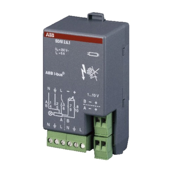
Page 6: Circuit Diagram
The PE conductor is brought out from the device to connect the protective conductor. 2.1.4 Assembly and installation The device is solely intended for operation in the Room Controller Basis Device. It can be snapped into any module slot. The mounting position can be selected as required. © 2004 ABB STOTZ-KONTAKT GmbH... -
Page 7: Lr/M 1.6.1 Light Controller Module, 2-Fold, 6 A
– Housing, colour Plastic housing, anthracite, halogen-free – Housing dimensions (WxHxD) 49 x 42 x 93 mm – Weight 0.08 kg CE norm – in accordance with the EMC guideline and the low voltage guideline © 2004 ABB STOTZ-KONTAKT GmbH... -
Page 8: Circuit Diagram
The PE conductor is brought out from the device to connect the protective conductor. 2.2.4 Assembly and installation The device is solely intended for operation in the Room Controller Basis Device. It can be snapped into any module slot. The mounting position can be selected as required. © 2004 ABB STOTZ-KONTAKT GmbH... -
Page 9: Ud/M 1.300.1 Universal Dim Actuator Module, 1-Fold, 300 Va
When connecting low voltage halogen lamps, ABB transformers are recommended. When the incoming supply is restarted (after disconnection from supply for more than approx. 10 seconds), the device conducts a load test and adapts the operating mode accordingly. -
Page 10: Circuit Diagram
PE conductor is brought out from the device to connect the protective conductor. 2.3.4 Assembly and installation The device is solely intended for operation in the Room Controller Basis Device. It can be snapped into any module slot. The mounting position can be selected as required. © 2004 ABB STOTZ-KONTAKT GmbH... -
Page 11: Planning And Application
Die Konstantlichtregelung wird immer dann aktiviert, wenn die ausgeschaltete Beleuchtung eingeschaltet wird (Objekt „Schalten“ erhält den Wert „1“). Einzige Ausnahme: Die „Nachlaufzeit bei inaktiver Regelung“ ist aktiv. Darüber hinaus kann die Regelung über das Objekt „Regelung aktiv/inaktiv“ aktiviert werden. © 2004 ABB STOTZ-KONTAKT GmbH... - Page 12 You may wish the lamps in the vicinity of the window to always be slightly darker than the lamps inside the room. This can be implemented by slaves whose brightness is adapted by the correction of the characteristic curve. © 2004 ABB STOTZ-KONTAKT GmbH...
-
Page 13: Presets
…”. A maximum of 4 preset values are available for each output: Retrieve preset1 Object “Call preset 1/2” = 0 Retrieve preset2 Object “Call preset 1/2” = 1 Retrieve preset3 Object “Call preset 3/4” = 0 Retrieve preset4 Object “Call preset 3/4” = 1 © 2004 ABB STOTZ-KONTAKT GmbH... - Page 14 Store preset1 Object “Set preset 1/2” = 0 Store preset2 Object “Set preset 1/2” = 1 Store preset3 Object “Set preset 3/4” = 0 Store preset4 Object “Set preset 3/4” = 1 © 2004 ABB STOTZ-KONTAKT GmbH...
-
Page 15: 8-Bit Lightscene
- Retrieve scene / store scene After a long push button action, the actuators receive a save command which causes them to store the current value issued by the actuator as a new scene value. © 2004 ABB STOTZ-KONTAKT GmbH... -
Page 16: Staircase Lighting Function
“1” “1” “1” switch” Fig. 9: Using the pumping function If the device receives a further ON command when the staircase lighting is switched on, the staircase lighting time is added to the remaining period. © 2004 ABB STOTZ-KONTAKT GmbH... -
Page 17: Correction Of Characteristic Curve
It is possible to parameterise the behaviour of the outputs on failure of the bus voltage. The function of the Room Controller is retained provided that the supply voltage (115 / 230 V AC or 12 V DC auxiliary voltage) is available. © 2004 ABB STOTZ-KONTAKT GmbH... -
Page 18: Reaction After Programming
Reaction after programming After programming, the device behaves in the same way as after bus voltage recovery (see above). The current setpoint value of the constant lighting control (Light Controller Module LR/M 1.6.1) will remain unchanged. © 2004 ABB STOTZ-KONTAKT GmbH... -
Page 19: Project Design And Programming
The parameter is visible if the value “yes” has been selected in the parameter “Status response of switching state”. If the status response is inverted (parameter value “yes”), the object “Status switch” has the following values: “0” Lighting is switched on ”1” Lighting is switched off © 2004 ABB STOTZ-KONTAKT GmbH... - Page 20 The supply voltage has failed if both the 115/230 V AC supply and the 12 V DC auxiliary voltage have failed. In this case, the Room Controller has no function. © 2004 ABB STOTZ-KONTAKT GmbH...
-
Page 21: Parameter Window: "Function
This parameter is visible if the additional function “Enable fct. ‘priority / forced operation’” has been activated. The brightness value is set here which is adopted when the object “Priority / forced operation” has the value “3” ( = “ON, activate forced operation”). © 2004 ABB STOTZ-KONTAKT GmbH... - Page 22 EIB / KNX Project design and programming When the forced operation is cancelled, the normal state of the output is restored. During the forced operation, the brightness value is continually calculated; only “Relative dimming” telegrams are ignored. © 2004 ABB STOTZ-KONTAKT GmbH...
-
Page 23: Function: "Relative Dimming
Parameter: “Switch OFF mode” It can be set how the lighting is switched off. The following table provides an overview: switch off Switching off as quickly as possible dimming off Switching off with the dimming ramp © 2004 ABB STOTZ-KONTAKT GmbH... - Page 24 It can be set here whether the lighting can be switched off by a dimming “DARKER” telegram once it has been switched on. If the parameter value “no” is selected, the brightness value remains at the lower dimming limit. © 2004 ABB STOTZ-KONTAKT GmbH...
-
Page 25: Function: "Brightness Values
Parameter: “Allow switching off via brightness values” If a brightness value is received that is equal to zero, it can be set here whether the lighting is switched off (“yes”) or remains at the lower dimming limit. © 2004 ABB STOTZ-KONTAKT GmbH... -
Page 26: More Detailed Functional Description
(= object “Call preset 1/2” receives telegram value “1”). Parameter: “Preset values 1/2” This parameter sets whether the dimmer jumps to the preset value as quickly as possible or whether the dimmer dims to the preset value using the transition time. © 2004 ABB STOTZ-KONTAKT GmbH... - Page 27 The object “Set preset 1/2” is enabled via this parameter. It is used to store the brightness value that is currently selected as the new preset value. Telegram value “0” stores preset1 while telegram value “1” stores preset2. The function of preset 3/4 is identical to preset 1/2. © 2004 ABB STOTZ-KONTAKT GmbH...
-
Page 28: Function: "Lighting Control
The lighting control can be deactivated by the user so that it can be manually operated. When the control is inactive, the light controller behaves like a normal dimming actuator except that the value “1” at the object “Telegr. switch” always activates the control function again. © 2004 ABB STOTZ-KONTAKT GmbH... -
Page 29: Parameter Window: "Control
It can be set in this parameter whether the control is “active” or “inactive” once the supply voltage of the device has recovered. In the setting “inactive”, the brightness value follows the setting in the “General” parameter window. © 2004 ABB STOTZ-KONTAKT GmbH... -
Page 30: Parameter Window: "Operating
This function should enable the user who has only temporarily left the room to restore the same lighting environment. It is particularly advisable if the control function is activated by a presence/movement detector. © 2004 ABB STOTZ-KONTAKT GmbH... -
Page 31: Function: "Slave Mode In Lighting Control
It can be set which effect the receipt of the telegram has on the active slave mode: In the setting “no reaction”, the receipt is ignored. In the setting “Slave mode can be deactivated”, the slave mode is deactivated. It can be reactivated by an ON telegram. © 2004 ABB STOTZ-KONTAKT GmbH... - Page 32 Parameter: “Slave mode after supply voltage recovery” It can be set in this parameter whether slave mode is “active” or “not active” after bus voltage recovery. If the slave function is “active”, the brightness value is polled after bus voltage recovery. © 2004 ABB STOTZ-KONTAKT GmbH...
-
Page 33: Function: "Staircase Lighting
(normal staircase lighting time). ‘Pumping’ is not taken into account. Supply voltage failure No function Supply voltage recovery As for bus voltage recovery Fig. 3: Progression of the brightness level during staircase lighting © 2004 ABB STOTZ-KONTAKT GmbH... -
Page 34: Parameter Window: "Staircase Lighting
In the setting “dimming down”, the dimming down time is started when the lighting is switched on (not for permanent ON). Parameter: “Brightness value during permanent ON” The brightness of the lighting can be set here (0...100%), while the object “Permanent ON” has the value “1”. © 2004 ABB STOTZ-KONTAKT GmbH... - Page 35 The lighting is switched on and the staircase lighting time is started. switched off The lighting is switched off. The output also follows this parameter on recovery of the bus voltage and after supply voltage recovery. © 2004 ABB STOTZ-KONTAKT GmbH...
-
Page 36: Function "Lightscene (8-Bit)
“Characteristic adjustment” The characteristic adjustment enables e.g. the adaptation of the dimming characteristic curve of the lamp to the sensitivity of the human eye. Further information about the function can be found under section 3.5. © 2004 ABB STOTZ-KONTAKT GmbH... - Page 37 The X value (input value) designates the object value. The Y value denotes the brightness value which is issued at this object value. The first X value is also defined with “1” while the last X value is always given the value “255”. © 2004 ABB STOTZ-KONTAKT GmbH...
-
Page 38: Detailed Description Of The Objects
Set setpoint value Light control 1 Bit (EIS1) If the device receives the value “1” via this object, the current light sensor value (actual value) is adopted as the new setpoint value of the control function. © 2004 ABB STOTZ-KONTAKT GmbH... - Page 39 Output A 1 Bit (EIS1) Used to disable the output to prevent unwanted operation. 4.11.2 Detailed description of the communication objects Object: “Telegr. switch”: 1 Bit (EIS1) This object switches the output on or off. © 2004 ABB STOTZ-KONTAKT GmbH...
- Page 40 (only Universal Dim Actuator Module UD/M 1.300.1) This object reports a general error. In the event of an error, the dimming actuator offers the possibility of providing detailed information on the bus about the cause of the error. Object values: © 2004 ABB STOTZ-KONTAKT GmbH...
- Page 41 (“1” = control active, “0” = control inactive). By writing to this object, the lighting control can be deactivated (“1”) and activated (“0”). When the control is deactivated, the brightness value initially remains unchanged. © 2004 ABB STOTZ-KONTAKT GmbH...
- Page 42 130 or 194 82h or B2h Set scene 3 191 or 255 AFh or FFh Set scene 64 Object: “Disable”: 1 Bit (EIS1) This object is used to disable the output in order to prevent unwanted operation. © 2004 ABB STOTZ-KONTAKT GmbH...
- Page 43 If this object receives the value “1”, telegrams to the objects “Telegr. switch” and “Relative dimming” are ignored. If the object value is “0”, these objects behave normally. On receipt of an object value, the output remains unchanged. © 2004 ABB STOTZ-KONTAKT GmbH...
-
Page 44: Appendix
Value table for object “Error code” 172 AC 173 AD 188 BC 189 BD 202 CA 203 CB 204 CC 205 CD 206 CE 218 DA 219 DB 220 DC 221 DD 222 DE 236 EC 237 ED © 2004 ABB STOTZ-KONTAKT GmbH... -
Page 45: Ordering Information
2CDG 110 012 R0011 583602 Module, 1-fold, 300 VA ⎯⎯⎯⎯⎯⎯⎯⎯⎯⎯⎯⎯⎯⎯⎯⎯⎯⎯⎯⎯⎯⎯⎯⎯⎯⎯⎯⎯⎯⎯⎯⎯⎯⎯⎯⎯⎯⎯⎯⎯⎯⎯⎯⎯⎯⎯⎯⎯⎯⎯ ABB STOTZ-KONTAKT GmbH P.O. Box 10 16 80, D-69006 Heidelberg 2004-11-04 Tel (06221) 701-607 Fax (06221) 701-724 www.abb.de/stotz-kontakt Technical Hotline: Tel (06221) 701-434 Email: eib.hotline@de.abb.com © 2004 ABB STOTZ-KONTAKT GmbH...
Need help?
Do you have a question about the i-bus EIB and is the answer not in the manual?
Questions and answers