baltur TBL 210P Original Instructions Manual
Double-stage diesel burners
Hide thumbs
Also See for TBL 210P:
- User instruction manual (120 pages) ,
- Manual user instructions (108 pages) ,
- Instruction manual for installation, use and maintenance (92 pages)
Table of Contents
Advertisement
Available languages
Available languages
ITALIANO
Manuale istruzioni per l'installazione, l'uso e la
Installation, use and maintenance instruction
ISTRUZIONI ORIGINALI (IT)
ORIGINAL INSTRUCTIONS (IT)
IT
manutenzione
EN
manual
BRUCIATORI DI GASOLIO BISTADIO
DOUBLE-STAGE DIESEL BURNERS
TBL 85P / P DACA
TBL 105P / P DACA
TBL 130P / P DACA
TBL 160P / P DACA
TBL 210P
TBL 260P
0006081053_201805
Advertisement
Chapters
Table of Contents

Related Manuals for baltur TBL 210P


Summary of Contents for baltur TBL 210P
- Page 1 Manuale istruzioni per l'installazione, l'uso e la manutenzione TBL 105P / P DACA Installation, use and maintenance instruction manual TBL 130P / P DACA TBL 160P / P DACA TBL 210P TBL 260P ISTRUZIONI ORIGINALI (IT) ORIGINAL INSTRUCTIONS (IT) 0006081053_201805...
-
Page 3: Table Of Contents
ITALIANO ITALIANO SOMMARIO Avvertenze per l'uso in condizioni di sicurezza ............................7 Caratteristiche tecniche ..................................10 Materiale a corredo ..................................11 Targa identificazione bruciatore............................... 11 Caratteristiche tecnico funzionali ..............................12 Caratteristiche costruttive ................................12 Campo di lavoro ....................................13 Descrizione componenti ..................................14 Quadro elettrico ....................................14 Dimensioni di ingombro ...................................15 Applicazione del bruciatore alla caldaia ..............................16 collegamento bruciatore alla linea alimentazione combustibile liquido ....................17... - Page 4 ITALIANO DICHIARAZIONE DI CONFORMITÀ CE0085: DVGW CERT GmbH, Josef-Wirmer Strasse 1-3-53123 Bonn (D) Dichiariamo che i nostri bruciatori ad aria soffiata di combustibili gassosi e misti, serie: BPM...; BGN…; BTG…; TBML...; Comist…; GI…; GI…Mist; Minicomist…; Sparkgas...; TBG..; IB..; TBR... (Variante: … LX, per basse emissioni NOx; -V per inverter, FGR per ricircolazione esterna fumi) rispettano i requisiti minimi imposti dalle Direttive e Regolamenti europei: •...
-
Page 5: Avvertenze Per L'uso In Condizioni Di Sicurezza
ITALIANO AVVERTENZE PER L'USO IN CONDIZIONI sull'apparecchio. • L'apparecchio non è adatto a essere usato da persone (bambini DI SICUREZZA compresi) le cui capacità fisiche, sensoriali o mentali siano ridotte, oppure con mancanza di esperienza o di conoscenza. SCOPO DEL MANUALE •... - Page 6 • L’eventuale riparazione dei prodotti dovrà essere effettuata • Prima di avviare il bruciatore e almeno una volta all’anno, solamente da un centro di assistenza autorizzato da BALTUR o far effettuare da personale professionalmente qualificato le dal suo distributore locale, utilizzando esclusivamente ricambi seguenti operazioni: originali.
- Page 7 ITALIANO RISCHI RESIDUI - Allorché si decida di non utilizzare l’apparecchio per un • Nonostante l'accurata progettazione del prodotto, nel rispetto certo periodo é opportuno spegnere l’interruttore elettrico delle norme cogenti e delle buone regole nell'impiego corretto di alimentazione a tutti i componenti dell’impianto che possono permanere dei rischi residui.
-
Page 8: Caratteristiche Tecniche
ITALIANO CARATTERISTICHE TECNICHE TBL 85P / P TBL 105P / P TBL 130P / P TBL 160P / P MODELLO TBL 210P TBL 260P DACA DACA DACA DACA Kg/h Portata termica minima 16.9 33.7 42.1 67.4 80.1 Kg/h Portata termica massima 71.7... -
Page 9: Materiale A Corredo
ITALIANO MATERIALE A CORREDO TBL 85P / P TBL 105P / P TBL 130P / P TBL 160P / P MODELLO TBL 210P TBL 260P DACA DACA DACA DACA Flangia attacco bruciatore Guarnizione isolante Prigionieri N°4 - M12 N°4 - M12 N°4 - M12... -
Page 10: Caratteristiche Tecnico Funzionali
ITALIANO CARATTERISTICHE TECNICO FUNZIONALI CARATTERISTICHE COSTRUTTIVE • Bruciatore a basse emissioni di NOx e CO secondo la normativa • Testa di combustione completa di boccaglio in acciaio inox. europea EN267. • Parte ventilante in lega leggera d'alluminio. • Regolazione dell'aria comburente e della testa di combustione. •... -
Page 11: Campo Di Lavoro
ITALIANO CAMPO DI LAVORO TBL 85P TBL 105P TBL 130P TBL 160P TBL 210P mbar 900 1000 1100 1200 1300 1400 1500 1600 1700 1800 1900 2000 2100 kg/h IMPORTANTE I campi di lavoro sono ottenuti su caldaie di prova rispondenti alla norma EN267 e sono orientativi per gli accoppiamenti bruciatore- caldaia. -
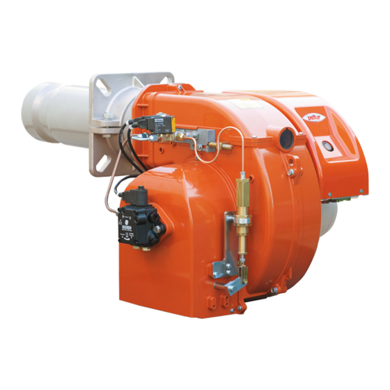
Page 12: Descrizione Componenti
ITALIANO DESCRIZIONE COMPONENTI Testa di combustione Guarnizione Flangia attacco bruciatore Dispositivo regolazione testata Elettrovalvola 2° stadio Elettrovalvola di sicurezza Elettrovalvola 1° stadio Cerniera Martinetto idraulico comando aria Servomotore regolazione aria (versione DACA) Pompa 12 bar Quadro elettrico Motore Targa identificazione bruciatore QUADRO ELETTRICO Apparecchiatura Trasformatore d'accensione... -
Page 13: Dimensioni Di Ingombro
TBL 85P / P DACA 1250 TBL 105P / P DACA 1250 TBL 130P / P DACA 1250 TBL 160P / P DACA 1300 TBL 210P 1300 TBL 260P 1300 Modello D min D max E Ø F Ø L min... -
Page 14: Applicazione Del Bruciatore Alla Caldaia
ITALIANO APPLICAZIONE DEL BRUCIATORE ALLA CALDAIA • Adeguare la posizione della flangia di attacco (19) allentando le viti (6), la testa del bruciatore dovrà penetrare nel focolare della misura consigliata dal costruttore del generatore. • Posizionare sul canotto la guarnizione isolante (13) interponendo la corda (2) tra la flangia e guarnizione. -
Page 15: Collegamento Bruciatore Alla Linea Alimentazione Combustibile Liquido
ITALIANO COLLEGAMENTO BRUCIATORE ALLA LINEA ALIMENTAZIONE COMBUSTIBILE LIQUIDO LINEA DI ALIMENTAZIONE Il valore della pressione di alimentazione del combustibile alla pompa del bruciatore non deve variare sia con bruciatore fermo che con bruciatore funzionante alla massima erogazione di combustibile richiesta dalla caldaia. Si può... - Page 16 ITALIANO TBL 85 - 105 .. IMPIANTO DI ALIMENTAZIONE PER GRAVITA' Serbatoio Tubo di aspirazione Tubazione di alimentazione Tubo di ritorno bruciatore Filtro a rete Dispositivo automatico Pompa intercettazione a bruciatore Degasificatore fermo Valvola unidirezionale L. Complessiva Metri Metri Øi 14 mm IMPIANTO A CADUTA CON ALIMENTAZIONE DALLA SOMMITA' DEL SERBATOIO Serbatoio Tubo di ritorno...
- Page 17 ITALIANO TBL 130 - 160 - 210 IMPIANTO DI ALIMENTAZIONE PER GRAVITA' Serbatoio Tubo di aspirazione Tubazione di alimentazione Tubo di ritorno bruciatore Filtro a rete Dispositivo automatico Pompa intercettazione a bruciatore fermo Degasificatore Valvola unidirezionale L. Complessiva Metri Metri Øi 16 mm IMPIANTO A CADUTA CON ALIMENTAZIONE DALLA SOMMITA' DEL SERBATOIO Serbatoio...
- Page 18 ITALIANO TBL 260 IMPIANTO DI ALIMENTAZIONE PER GRAVITA' Serbatoio Tubo di aspirazione Tubazione di alimentazione Tubo di ritorno bruciatore Filtro a rete Dispositivo automatico Pompa intercettazione a bruciatore Degasificatore fermo Valvola unidirezionale L. Complessiva Metri Metri Øi 16 mm IMPIANTO A CADUTA CON ALIMENTAZIONE DALLA SOMMITA' DEL SERBATOIO Serbatoio Tubo di ritorno Filtro a rete...
-
Page 19: Pompa Ausiliaria
TBL 85P - 85P DACA 1 bar TBL 105P - 105P DACA 1,5 bar TBL 130P - 130P DACA 1,5 bar TBL 160P - 160P DACA 2 bar TBL 210P 2,5 bar TBL 260P 5 bar 17 / 38 0006081053_201805... -
Page 20: Collegamenti Elettrici
ITALIANO COLLEGAMENTI ELETTRICI • Tutti i collegamenti devono essere eseguiti con filo elettrico flessibile. • Le linee elettriche devono essere distanziate dalle parti calde. • L’installazione del bruciatore è consentita solo in ambienti con grado di inquinamento 2 come indicato nell’allegato M della norma EN 60335-1:2008-07. - Page 21 ITALIANO CAUTELA / AVVERTENZE Gli alloggiamenti dei cavi per le spine sono previsti rispettivamente per cavo Ø 9,5÷10 mm e Ø 8,5÷9 mm, questo per assicurare il grado di protezione IP 54 (Norma CEI EN60529) relativamente al quadro elettrico. • Per richiudere il coperchio del quadro elettrico, avvitare le viti (1) esercitando una coppia di serraggio di circa 5 Nm per assicurare la corretta tenuta.
-
Page 22: Descrizione Del Funzionamento
ITALIANO DESCRIZIONE DEL FUNZIONAMENTO Viceversa se la temperatura o pressione scende sotto i valori di taratura del termostato o pressostato caldaia, il bruciatore si Quando un bruciatore bistadio è installato su una caldaia per riavvierà. produzione di acqua calda ad uso riscaldamento, deve essere Se durante il funzionamento dovesse esserci un'interruzione di collegato in modo da lavorare a regime normale con entrambe le fiamma per almeno un secondo, interviene la fotoresistenza che... -
Page 23: Primo Riempimento Circuito Idraulico
ITALIANO PRIMO RIEMPIMENTO CIRCUITO • Premere ora sulla parte mobile del teleruttore del motore per mettere in funzione il motore stesso e quindi la pompa. Attendere IDRAULICO che la pompa abbia aspirato una quantità di lubrificante pari a 1 o 2 bicchieri, quindi fermare. Questa operazione ha lo scopo TUBAZIONE DEL COMBUSTIBILE di evitare il funzionamento della pompa a secco e di aumentare il potere aspirante. -
Page 24: Accensione E Regolazione
ITALIANO ACCENSIONE E REGOLAZIONE passa automaticamente, secondo il programma stabilito dal programmatore, al secondo stadio. Prima dell'accensione è necessario assicurarsi che: • Regolare l’aria nella quantità necessaria per assicurare una • Verificare che gli ugelli applicati sul bruciatore siano adatti alla buona combustione. -
Page 25: Controlli
ITALIANO CONTROLLI ma, la fotoresistenza non vede la luce e, nel tempo determinato dal programma dell’apparecchiatura, si porta in blocco. Avviato il bruciatore occorre controllare i dispositivi di sicurezza, • L’apparecchiatura si può sbloccare solo con intervento manuale fotoresistenza, componenti di blocco, termostati. premendo l’apposito pulsante. -
Page 26: Regolazione Aria Sulla Testa Di Combustione
TBL 130P - P DACA 103 ÷ 67 1 ÷ 5 TBL 160P - P DACA 127,5 ÷ 91,5 1 ÷ 5 TBL 210P 132 ÷ 96 1 ÷ 5 TBL 260P 132 ÷ 96 1 ÷ 5 PERICOLO / ATTENZIONE Le regolazioni sono indicative;... -
Page 27: Particolari Pompa
ITALIANO PARTICOLARI POMPA AJ4 - AJ6 1 Elettrovalvola (normalmente chiusa) 2 Attacco manometro e sfogo aria (1/8"G) 3 Vite regolazione pressione 3.1 Asportare il dado per accedere alla vite di regolazione della pressione (11÷14 bar) 4 Ritorno 4.1 Ritorno con grano di by-pass interno 5 Aspirazione 6 Mandata all'ugello 7 Attacco vuotometro (1/8"G) -
Page 28: Martinetto Oscillante
ITALIANO MARTINETTO OSCILLANTE REGOLAZIONE POSIZIONE DELLA SERRANDA ARIA PRIMO STADIO • Per aumentare la portata d’aria erogata, agire sulla ghiera (3) con rotazione antioraria, utilizzare la controchiave sul corpo (1) del martinetto per evitare un’eccessiva sollecitazione sul perno dell’occhiello (9). •... -
Page 29: Regolazione Camme Servomotore Sqn72.2B4A20
ITALIANO REGOLAZIONE CAMME SERVOMOTORE SQN 72.2B4A20 SQN72.2B4A20 Per modificare la regolazione delle camme utilizzate, si agisce sui rispettivi anelli (I - II - III ...) l'indice dell'anello indica sulla rispettiva scala di riferimento l'angolo di rotazione impostato per ogni camma. Perno inserzione ed esclusione accoppiamento motore - albero camme Scala di riferimento... -
Page 30: Apparecchiatura Di Comando E Controllo Lmo
ITALIANO APPARECCHIATURA DI COMANDO E CONTROLLO LMO... FUNZIONAMENTO. Il pulsante di sblocco «EK...» è l’elemento principale per poter accedere a tutte le ROSSO funzioni di diagnostica (attivazione e disattivazione), oltre a sbloccare il dispositivo GIALLO di comando e controllo. VERDE Il «LED»... - Page 31 ITALIANO DIAGNOSI DELLE CAUSE DI MALFUNZIONAMENTO E BLOCCO. In caso di blocco bruciatore nel pulsante di sblocco sarà fissa la luce rossa. Premendo per più di 3 sec. la fase di diagnosi verrà attivata (luce rossa con lampeggio rapido), nella tabella sottostante viene riportato il significato della causa di blocco o malfunzionamento in funzione del numero di lampeggi (sempre colore rosso).
-
Page 32: Manutenzione
ITALIANO MANUTENZIONE Effettuare almeno una volta all’anno e comunque in conformità alle norme vigenti, l’analisi dei gas di scarico della combustione verificando la correttezza dei valori di emissioni. • Pulire le serrande aria, il pressostato aria con presa di pressione ed il relativo tubo se presenti. -
Page 33: Tempi Di Manutenzione
ITALIANO TEMPI DI MANUTENZIONE Descrizione particolare Azione da eseguire Gasolio TESTA DI COMBUSTIONE CONTROLLO VISIVO, INTEGRITA' CERAMICHE, SMERIGLIATURA ESTREMITA', ELETTRODI ANNUO VERIFICARE DISTANZA, VERIFICARE CONNESSIONE ELETTRICA DISCO FIAMMA CONTROLLO VISIVO INTEGRITA' EVENTUALI DEFORMAZIONI, PULIZIA ANNUO COMPONENTI TESTA COMBUSTIONE CONTROLLO VISIVO INTEGRITA' EVENTUALI DEFORMAZIONI, PULIZIA ANNUO UGELLI COMBUSTIBILE LIQUIDO SOSTITUZIONE... -
Page 34: Vita Attesa
ITALIANO VITA ATTESA La vita attesa dei bruciatori e dei relativi componenti dipende molto dal tipo di applicazione su cui il bruciatore è installato, dai cicli della potenza erogata, dalle condizioni dell’ambiente in cui si trova, dalla frequenza e modalità di manutenzione, ecc. ecc. Le normative relative ai componenti di sicurezza, prevedono una vita attesa di progetto espressa in cicli e/o anni di funzionamento. -
Page 35: Istruzioni Per L'accertamento Delle Cause Di Irregolarità Nel Funzionamento E La Loro Eliminazione
ITALIANO ISTRUZIONI PER L'ACCERTAMENTO DELLE CAUSE DI IRREGOLARITÀ NEL FUNZIONAMENTO E LA LORO ELIMINAZIONE IRREGOLARITÁ POSSIBILE CAUSA RIMEDIO L'apparecchio va in "blocco" con la Fotoresistenza interrotta o sporca Pulire o sostituire. fiamma (lampada rossa accesa) il guasto di fumo. Controllare tutti i passaggi dei è... - Page 36 ITALIANO IRREGOLARITÁ POSSIBILE CAUSA RIMEDIO Fiamma difettosa con presenza di faville. Pressione di polverizzazione Ripristinarla al valore previsto. troppo bassa. Diminuire l’aria comburente Eccesso di aria comburente. Pulire o sostituire. Ugello inefficiente perché sporco Scaricare l'acqua dalla cisterna o logoro. servendosi di una pompa adatta.
-
Page 37: Tabella Portata Ugelli
ITALIANO TABELLA PORTATA UGELLI Ugello Pressione Pompa bar Ugello G.P.H. G.P.H. 0,40 1,18 1,27 1,36 1,44 1,52 1,59 1,67 1,73 1,80 1,86 1,92 1,98 2,04 2,10 2,15 2,20 2,25 2,31 2,36 2,40 2,45 0,40 0,50 1,47 1,59 1,70 1,80 1,90 1,99 2,08 2,17 2,25 2,33 2,40 2,48 2,55 2,62 2,69 2,75 2,82 2,88 2,94 3,00 3,05 0,50 0,60 1,77 1,91 2,04 2,16 2,28 2,39 2,50 2,60 2,70 2,79 2,88 2,97 3,06 3,14 3,22 3,30 3,38 3,46 3,53 3,61 3,68... -
Page 38: Schemi Elettrici
ITALIANO SCHEMI ELETTRICI 36 / 38 0006081053_201805... - Page 39 ITALIANO 37 / 38 0006081053_201805...
- Page 40 ITALIANO APPARECCHIATURA Colore serie fili GNYE VERDE / GIALLO FOTORESISTENZA / ELETTRODO DI IONIZZAZIONE / FOTOCELLULA UV RELE’ TERMICO BRUNO FU1÷4 FUSIBILI NERO SPIA BLOCCO ESTERNA / LAMPADA FUNZIONAMENTO CONNETTORE NERO CON SOVRASTAMPA RESISTENZE AUSILIARIE L1 - L2- L3 Fasi SPIA DI FUNZIONAMENTO N - Neutro SPIA DI BLOCCO...
- Page 41 ENGLISH ENGLISH SUMMARY Warnings for use in safety conditions ..............................7 Technical specifications ..................................10 Standard accessories ..................................11 Burner identification plate ................................11 Technical functional characteristics ..............................12 Design characteristics ..................................12 Operating range ....................................13 Component description ...................................14 Electrical panel ....................................14 Overall dimensions ..................................15 Burner connection to the boiler ................................16 connecting the burner to the liquid fuel supply line ..........................17 Supply line .......................................17...
- Page 42 ENGLISH DECLARATION OF CONFORMITY CE0085: DVGW CERT GmbH, Josef-Wirmer Strasse 1-3-53123 Bonn (D) We hereby declare under our own responsibility, that our blown air burners fired by gas and dual fuel, series: BPM...; BGN…; BTG…; TBML...; Comist…; GI…; GI…Mist; Minicomist…; Sparkgas...; TBG..; IB..; TBR... (Variant: …...
-
Page 43: Warnings For Use In Safety Conditions
ENGLISH WARNINGS FOR USE IN SAFETY have access to, through a responsible person, the information concerning their safety, surveillance and instructions concerning CONDITIONS equipment use. • Children must be watched over to prevent them from playing PURPOSE OF THIS MANUAL with the equipment. - Page 44 Contact only qualified personnel. accordance with the law in force. • Any product repairs must only be carried out by BALTUR - Check the adjustment and safety devices are working authorised assistance centres or by its local distributor using properly.
- Page 45 ENGLISH RESIDUAL RISKS - in case of PVC sheath, at least type H05VV-F; • Even though the product was designed in compliance with the - in case of rubber sheath, at least type H05RR-F; obligatory standards, residual risks may still be present during - without any sheath at least type FG7 or FROR.
-
Page 46: Technical Specifications
ENGLISH TECHNICAL SPECIFICATIONS TBL 85P / P TBL 105P / P TBL 130P / P TBL 160P / P MODEL TBL 210P TBL 260P DACA DACA DACA DACA Kg/h Minimum thermal flow 16.9 33.7 42.1 67.4 80.1 Kg/h Maximum thermal flow 71.7... -
Page 47: Standard Accessories
ENGLISH STANDARD ACCESSORIES TBL 85P / P TBL 105P / P TBL 130P / P TBL 160P / P MODEL TBL 210P TBL 260P DACA DACA DACA DACA Burner connection flange Insulating gasket Stud bolts N°4 - M12 N°4 - M12 N°4 - M12... -
Page 48: Technical Functional Characteristics
ENGLISH TECHNICAL FUNCTIONAL CHARACTERISTICS DESIGN CHARACTERISTICS • Gas burner with low NOx and CO emissions in accordance with • Combustion head complete with stainless steel nozzle. European standard EN267. • Ventilating part in light aluminium alloy. • Combustion air and combustion head regulation. •... -
Page 49: Operating Range
ENGLISH OPERATING RANGE TBL 85P TBL 105P TBL 130P TBL 160P TBL 210P mbar 900 1000 1100 1200 1300 1400 1500 1600 1700 1800 1900 2000 2100 kg/h IMPORTANT The operating ranges are obtained from test boilers corresponding to Standard EN267 and are indicative of the burner-boiler combination. -
Page 50: Component Description
ENGLISH COMPONENT DESCRIPTION Combustion head Seal Burner connection flange Combustion head adjustment device 2nd stage solenoid valve Safety solenoid valve 1st stage solenoid valve Hinge Hydraulic air control jack Air regulation servomotor (DACA version) 12-bar pump Electrical panel Motor Burner identification plate ELECTRICAL PANEL Control box Ignition transformer... -
Page 51: Overall Dimensions
TBL 85P / P DACA 1250 TBL 105P / P DACA 1250 TBL 130P / P DACA 1250 TBL 160P / P DACA 1300 TBL 210P 1300 TBL 260P 1300 Model D min D max E Ø F Ø L min... -
Page 52: Burner Connection To The Boiler
ENGLISH BURNER CONNECTION TO THE BOILER • Adjust the position of the coupling flange (19) by loosening the screws (6) so that the burner head enters the furnace to the extent recommended by the generator manufacturer. • Position the insulating gasket (13) on the sleeve, by inserting the cord (2) between the flange and the gasket. -
Page 53: Connecting The Burner To The Liquid Fuel Supply Line
ENGLISH CONNECTING THE BURNER TO THE LIQUID FUEL SUPPLY LINE SUPPLY LINE The fuel supply pressure to the burner pump must not change both with burner off and with working burner at the maximum fuel output required by the boiler. The supply circuit can be realized without pressure regulator, using the dedicated hydraulic diagram. - Page 54 ENGLISH TBL 85 - 105 .. GRAVITY SUPPLY SYSTEM Serbatoio Suction pipe Feeding pipe Burner return pipe Mesh filter Automatic shut-off device with Pompa burner off Degasificatore Unidirectional valve Total L. Meters Meters Øi 14 mm SIPHON FEED SYSTEM WITH FEED FROM THE TOP OF THE TANK Serbatoio Return pipe Mesh filter...
- Page 55 ENGLISH TBL 130 - 160 - 210 GRAVITY SUPPLY SYSTEM Serbatoio Suction pipe Feeding pipe Burner return pipe Mesh filter Automatic shut-off device with Pompa burner off Degasificatore Unidirectional valve Total L. Meters Meters Øi 16 mm SIPHON FEED SYSTEM WITH FEED FROM THE TOP OF THE TANK Serbatoio Return pipe Mesh filter...
- Page 56 ENGLISH TBL 260 GRAVITY SUPPLY SYSTEM Serbatoio Suction pipe Feeding pipe Burner return pipe Mesh filter Automatic shut-off device with Pompa burner off Degasificatore Unidirectional valve Total L. Meters Meters Øi 16 mm SIPHON FEED SYSTEM WITH FEED FROM THE TOP OF THE TANK Serbatoio Return pipe Mesh filter...
-
Page 57: Auxiliary Pump
TBL 85P - 85P DACA 1 bar TBL 105P - 105P DACA 1.5 bar TBL 130P - 130P DACA 1.5 bar TBL 160P - 160P DACA 2 bar TBL 210P 2.5 bar TBL 260P 5 bar 17 / 38 0006081053_201805... -
Page 58: Electrical Connections
ENGLISH ELECTRICAL CONNECTIONS • It is advisable to make all connections with flexible electric wire. • The power lines must be distanced from the hot parts. • The burner installation is allowed only in environments with pollution degree 2 as indicated in annex M of the EN 60335- 1:2008-07 regulation. - Page 59 ENGLISH CAUTION / WARNINGS The housings for the cables for the plugs are provided respectively for cable Ø 9.5÷10 mm and Ø 8.5÷9 mm, this ensures the protection rating is IP 54 (Standard IEC EN60529) for the electrical panel. • To reclose the electrical panel lid, fix the screws (1) with a torque of about 5 Nm to ensure the correct seal.
-
Page 60: Operating Description
ENGLISH OPERATING DESCRIPTION The ignition phase is repeated in this manner and, if the flame reignites normally, the burner will return to normal operation. When the two-stage burner is installed on a boiler for the Otherwise the equipment will shut-down automatically. production of hot water for heating purposes, it must be connected If the program is interrupted, due to a power supply failure, so it can operate under normal conditions with both flames,... -
Page 61: First Hydraulic Circuit Filling
ENGLISH FIRST HYDRAULIC CIRCUIT FILLING • Now press on the mobile part of the motor remote control switch in order to start up the motor and therefore the pump. Wait until the pump has sucked in an amount of lubricant equal to 1 or 2 FUEL PIPES glassfuls, then stop. -
Page 62: Starting Up And Regulation
ENGLISH STARTING UP AND REGULATION be based on the colour of the flame. • Regulate to obtain a light orange flame avoiding a red flame Before starting up, make sure that: with smoke, or a white flame with air excess. •... -
Page 63: Controls
ENGLISH CONTROLS • Keep the photoresistor darkened to restart the burner, but if the photoresistor does see the light within the time preset by the After starting the burner, check the safety devices, photoresistor, control device, the burner will lock-out. lock components, thermostats. -
Page 64: Air Regulation On The Combustion Head
TBL 130P - P DACA 103 ÷ 67 1 ÷ 5 TBL 160P - P DACA 127,5 ÷ 91,5 1 ÷ 5 TBL 210P 132 ÷ 96 1 ÷ 5 TBL 260P 132 ÷ 96 1 ÷ 5 DANGER / ATTENTION The adjustments are indicative only;... -
Page 65: Details Of Pumps
ENGLISH DETAILS OF PUMPS AJ4 - AJ6 Solenoid valve (normally closed) 2 Pressure gauge connector and air vent (1/8”G) 3 Pressure adjusting screw 3.1 Remove the nut to access the pressure adjusting screw (11-14 bar) 4 Return 4.1 Return with inner by-pass dowel 5 Suction 6 Delivery to nozzle Vacuum gauge connector (1/8”G) -
Page 66: Oscillating Jack
ENGLISH OSCILLATING JACK ADJUSTMENT OF FIRST STAGE AIR DUMPER POSITION • To increase the flow rate, turn ring nut (3) anticlockwise using the counter wrench on the body (1) of the jack to avoid putting excessive stress on the eyelet pin (9). •... -
Page 67: Servomotor Cams Adjustment Sqn72.2B4A20
ENGLISH SERVOMOTOR CAMS ADJUSTMENT SQN 72.2B4A20 SQN72.2B4A20 To adjust the setting of the cams used, use the corresponding rings (I - II - III). The scale on the ring indicates the reference scale of the rotation angle set for each cam. Motor-camshaft coupling On/Off pin Reference scale Position indicator... -
Page 68: Control And Command Equipment Lmo
ENGLISH CONTROL AND COMMAND EQUIPMENT LMO... OPERATION. The reset button «EK...» is the main element to access all diagnostics functions (activation and deactivation) and serves to unlock the command and control device. YELLOW The multi-coloured «LED» indicates the command and control device status during GREEN both operation and diagnostics functions. - Page 69 ENGLISH MALFUNCTION AND LOCK CAUSE DIAGNOSTICS. In the event of a burner lock-out, the red light on the reset button will be fixed. To activate the diagnosis phase (red light blinking fast) press the button for more than 3 seconds. The table below indicates the meaning of the block or fault cause according to the number of flashings (always red).
-
Page 70: Maintenance
ENGLISH MAINTENANCE Analyse combustion gases and check that the emission values are correct at least once a year, in compliance with current law. • Clean air dampers, the air pressure switch with pressure port and the relevant pipe, if any. •... -
Page 71: Maintenance Time
ENGLISH MAINTENANCE TIME Part description Action to be performed Diesel COMBUSTION HEAD VISUAL INSPECTION OF THE INTEGRITY OF CERAMICS. TIP GRINDING, CHECK ELECTRODES YEARLY DISTANCE, CHECK ELECTRICAL CONNECTION FLAME DISC INTEGRITY VISUAL CHECK FOR ANY DEFORMATIONS, CLEANING, YEARLY COMBUSTION HEAD COMPONENTS INTEGRITY VISUAL CHECK FOR ANY DEFORMATIONS, CLEANING, YEARLY LIQUID FUEL NOZZLES... -
Page 72: Expected Lifespan
ENGLISH EXPECTED LIFESPAN The expected lifespan of burners and relevant components depends very much from the type of application on which the burner is installed, from cycles of delivered power, from the conditions of the environment in which it is located, from maintenance frequency and mode, etc. -
Page 73: Instructions For Determining The Cause Leading To Irregularities In The Operation And Their Elimination
ENGLISH INSTRUCTIONS FOR DETERMINING THE CAUSE LEADING TO IRREGULARITIES IN THE OPERATION AND THEIR ELIMINATION IRREGULARITY POSSIBLE CAUSE REMEDY The equipment locks out with the flame Photoresistor severed or fouled Clean or replace. on (red lamp on). The fault is in the flame with smoke. - Page 74 ENGLISH IRREGULARITY POSSIBLE CAUSE REMEDY Defective flame with sparks. Spraying pressure is too low. Restore it at the required value. Too much combustion air. Reduce combustion air Nozzle inefficient because dirty or Clean or replace. worn. Drain water from the tank using Water in the fuel.
-
Page 75: Nozzle Flow Rate Table
ENGLISH NOZZLE FLOW RATE TABLE Nozzle Pump pressure in bar Nozzle G.P.H. G.P.H. 0,40 1,18 1,27 1,36 1,44 1,52 1,59 1,67 1,73 1,80 1,86 1,92 1,98 2,04 2,10 2,15 2,20 2,25 2,31 2,36 2,40 2,45 0,40 0,50 1,47 1,59 1,70 1,80 1,90 1,99 2,08 2,17 2,25 2,33 2,40 2,48 2,55 2,62 2,69 2,75 2,82 2,88 2,94 3,00 3,05 0,50 0,60 1,77 1,91 2,04 2,16 2,28 2,39 2,50 2,60 2,70 2,79 2,88 2,97 3,06 3,14 3,22 3,30 3,38 3,46 3,53 3,61 3,68... -
Page 76: Wiring Diagrams
ENGLISH WIRING DIAGRAMS 36 / 38 0006081053_201805... - Page 77 ENGLISH 37 / 38 0006081053_201805...
- Page 78 ENGLISH APPARECCHIATURA Wire series colour GNYE GREEN / YELLOW PHOTORESISTOR / IONISATION ELECTRODE / UV PHOTOCELL BLUE THERMAL RELAY BROWN FU1÷4 FUSES BLACK EXTERNAL LOCK INDICATOR LIGHT/ AUXILIARY HEATING BLACK CONNECTOR WITH OVERPRINT ELEMENT OPERATION LAMP L1 - L2- L3 Phases OPERATION INDICATOR LIGHT N - Neutral LOCK-OUT WARNING LIGHT...
- Page 80 BALTUR S.P.A. Via Ferrarese, 10 44042 Cento (Fe) - Italy Tel. +39 051-6843711 Fax. +39 051-6857527/28 www.baltur.it info@baltur.it Il presente catalogo riveste carattere puramente indicativo. La casa, pertanto, si riserva ogni possibilità di modifica dei dati tecnici e di quant'altro in esso riportato.
Need help?
Do you have a question about the TBL 210P and is the answer not in the manual?
Questions and answers