Table of Contents
Advertisement
Available languages
Available languages
Quick Links
Advertisement
Chapters
Table of Contents

Subscribe to Our Youtube Channel
Related Manuals for baltur TBL 18


Summary of Contents for baltur TBL 18
- Page 1 BRUCIATORI DI GASOLIO MONOSTADIO SINGLE-STAGE DIESEL BURNERS ITALIANO TBL 18 Manuale istruzioni per l'installazione, l'uso e la manutenzione TBL 26 Instruction manual for installation, use and maintenance TBL 35 ISTRUZIONI ORIGINALI (IT) ORIGINAL INSTRUCTIONS (IT) 0006160431_202112...
-
Page 3: Table Of Contents
ITALIANO ITALIANO SOMMARIO Avvertenze per l'uso in condizioni di sicurezza ..............................2 Caratteristiche tecniche ......................................6 Materiale a corredo ......................................6 Descrizione componenti ....................................7 Caratteristiche tecnico funzionali ..................................9 Caratteristiche costruttive ....................................9 Campo di lavoro .......................................9 Dimensioni di ingombro ....................................11 Dimensioni di ingombro ....................................12 Applicazione del bruciatore alla caldaia ................................13 collegamento bruciatore alla linea alimentazione combustibile liquido ........................14 Linea di alimentazione....................................14... -
Page 4: Avvertenze Per L'uso In Condizioni Di Sicurezza
ITALIANO AVVERTENZE PER L'USO IN CONDIZIONI DI processo regolamentato dalla EN 746-2, Si prega di contattare gli uffici commerciali Baltur. SICUREZZA • La data di produzione dell'apparecchio (mese, anno) sono indicati sulla targa identificazione bruciatore presente sull'apparecchio. SCOPO DEL MANUALE •... - Page 5 • L’eventuale riparazione dei prodotti dovrà essere effettuata operazioni: solamente da un centro di assistenza autorizzato da BALTUR o dal - Tarare la portata di combustibile del bruciatore secondo la suo distributore locale, utilizzando esclusivamente ricambi originali.
- Page 6 ITALIANO RISCHI RESIDUI Dichiariamo che i nostri bruciatori ad aria soffiata di combustibili • Nonostante l'accurata progettazione del prodotto, nel rispetto delle gassosi, liquidi e misti, rispettano i requisiti essenziali imposti norme cogenti e delle buone regole nell'impiego corretto possono dalle Direttive e Regolamenti europei e sono conformi alle permanere dei rischi residui.
- Page 7 ITALIANO A CURA DELL'INSTALLATORE (fare riferimento a EN 60947-5-1: 2016, Allegato K). • Installare un idoneo sezionatore per ciascuna linea di alimentazione - Si raccomanda che il dispositivo di arresto di emergenza sia di del bruciatore. colore rosso e la superficie dietro di esso sia di colore giallo. •...
-
Page 8: Caratteristiche Tecniche
ITALIANO CARATTERISTICHE TECNICHE MODELLO TBL 18 TBL 26 TBL 35 Kg/h Portata minima 15.1 Kg/h Portata massima 17.7 26.1 32.9 Potenza termica minima Potenza termica massima mg/kWh ³) emissioni Classe 2 Classe 2 Classe 2 Viscositá 1,5° E - 20° C 1,5°... -
Page 9: Descrizione Componenti
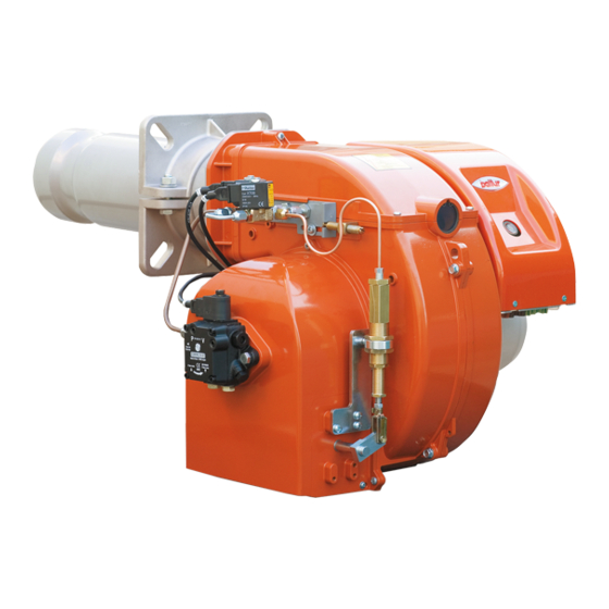
ITALIANO DESCRIZIONE COMPONENTI TBL 18 Testa di combustione Guarnizione Flangia attacco bruciatore Dispositivo regolazione testata Elettrovalvola Coperchio chiocciola Pompa combustibile liquido Quadro elettrico pannello di comando Motore ventola Oblò ispezione fiamma Targa identificazione bruciatore TBL 26 Apparecchiatura Trasformatore d'accensione Contattore motore (Solo con alimentazione trifase) Relè... - Page 10 ITALIANO Testa di combustione TBL 35 Guarnizione Flangia attacco bruciatore Dispositivo regolazione testata Elettrovalvola Coperchio chiocciola Pompa combustibile liquido Quadro elettrico pannello di comando Motore ventola Oblò ispezione fiamma Targa identificazione bruciatore Apparecchiatura Trasformatore d'accensione Contattore motore (Solo con alimentazione trifase) Relè...
-
Page 11: Caratteristiche Tecnico Funzionali
• Display visualizzatore della sequenza di funzionamento e del codice errore in caso di blocco. • Coperchio di protezione in materiale plastico insonorizzante. CAMPO DI LAVORO TBL 18 mbar / hPa 250 kW IMPORTANTE I campi di lavoro sono ottenuti su caldaie di prova rispondenti alla norma EN267 e sono orientativi per gli accoppiamenti bruciatore-caldaia. - Page 12 ITALIANO TBL 26 mbar / hPa TBL 35 mbar / hPa IMPORTANTE I campi di lavoro sono ottenuti su caldaie di prova rispondenti alla norma EN267 e sono orientativi per gli accoppiamenti bruciatore-caldaia. Per il corretto funzionamento del bruciatore le dimensioni della camera di combustione devono essere rispondenti alla normativa vigente; in caso contrario vanno consultati i costruttori.
-
Page 13: Dimensioni Di Ingombro
ITALIANO DIMENSIONI DI INGOMBRO TBL 18 TBL 26 Modello TBL 18 TBL 26 Modello E Ø F Ø TBL 18 100 ÷ 240 TBL 26 100 ÷ 255 Modello LØ TBL 18 170 ÷ 210 TBL 26 170 ÷ 210... - Page 14 ITALIANO DIMENSIONI DI INGOMBRO Ø N Ø L Modello TBL 35 Modello E Ø F Ø TBL 35 120 ÷ 370 Modello LØ TBL 35 200 ÷ 245 12 / 30 0006160431_202112...
-
Page 15: Applicazione Del Bruciatore Alla Caldaia
ITALIANO APPLICAZIONE DEL BRUCIATORE ALLA CALDAIA • Adeguare la posizione della flangia di attacco (19) allentando le viti (6), la testa del bruciatore dovrà penetrare nel focolare della misura consigliata dal costruttore del generatore. • Posizionare sul canotto la guarnizione isolante (13) interponendo la corda (2) tra la flangia e guarnizione. -
Page 16: Collegamento Bruciatore Alla Linea Alimentazione Combustibile Liquido
ITALIANO COLLEGAMENTO BRUCIATORE ALLA LINEA In alcuni casi (eccessiva distanza o dislivello) è necessario effettuare l'impianto con un circuito di alimentazione ad "anello", con pompa ALIMENTAZIONE COMBUSTIBILE LIQUIDO ausiliaria, evitando quindi il collegamento diretto della pompa del bruciatore alla cisterna. LINEA DI ALIMENTAZIONE In questo caso la pompa ausiliaria può... - Page 17 ITALIANO IMPIANTO A CADUTA CON ALIMENTAZIONE DALLA SOMMITÁ DEL SERBATOIO 1 Serbatoio combustibile. 3 Filtro a rete. 4 Bruciatore. 6 Tubo di aspirazione. 7 Tubo di ritorno del bruciatore. 8 Dispositivo automatico intercettazione combustibile a bruciatore fermo. 9 Valvola unidirezionale. 10 Valvola di fondo.
-
Page 18: Primo Riempimento Circuito Idraulico
ITALIANO PRIMO RIEMPIMENTO CIRCUITO IDRAULICO relative saracinesche. • Il bruciatore è così pronto per essere avviato. Dopo aver controllato che i tappi di protezione in plastica posti dentro gli attacchi della pompa siano stati asportati, procedere come segue: • Portare nella posizione “O” l’interruttore posto sul bruciatore, evitando così... -
Page 19: Collegamenti Elettrici
ITALIANO COLLEGAMENTI ELETTRICI • Le linee elettriche devono essere distanziate dalle parti calde. • L’installazione del bruciatore è consentita solo in ambienti con grado di inquinamento 2 come indicato nella norma EN 60204-1. • Le sezioni dei conduttori non specificati sono da considerarsi di 0,75 mm². -
Page 20: Descrizione Del Funzionamento
ITALIANO DESCRIZIONE DEL FUNZIONAMENTO Il bruciatore è a funzionamento completamente automatico; chiudendo l’interruttore generale e quello del quadro di comando il bruciatore viene inserito. La posizione di “blocco” è una posizione di sicurezza in cui il bruciatore si porta automaticamente, quando qualche particolare del bruciatore o dell’impianto è... -
Page 21: Accensione E Regolazione
ITALIANO ACCENSIONE E REGOLAZIONE comando, non compare regolarmente la fiamma. • Il blocco comporta l’arresto immediato del motore e quindi del bruciatore, Prima dell'accensione è necessario assicurarsi che: e l’accensione della relativa spia di blocco. • Verificare che la tensione della linea elettrica corrisponda a Per controllare l’efficienza del sensore fiamma e della relativa spia di quella richiesta dal costruttore e, che tutti i collegamenti elettrici blocco, operare come segue:... -
Page 22: Controlli
ITALIANO CONTROLLI Avviato il bruciatore occorre controllare i dispositivi di sicurezza, fotoresistenza, componenti di blocco, termostati. • Il dispositivo di controllo della fiamma, deve essere in grado di intervenire durante il funzionamento del bruciatore, nel caso non ci sia presenza di fiamma. •... -
Page 23: Schema Di Regolazione Distanza Disco Elettrodi
SCHEMA DI REGOLAZIONE DISTANZA DISCO ELETTRODI Dopo aver montato l'ugello, verificare il corretto posizionamento di elettrodi e disco, secondo le quote indicate in mm.E' opportuno eseguire una verifica delle quote dopo ogni TBL 18 intervento sulla testa. TBL 18 DANFOSS B 60° 3,00 GPH TBL 26 DANFOSS B 60°... -
Page 24: Schema Di Principio Circuito Idraulico
ITALIANO SCHEMA DI PRINCIPIO CIRCUITO IDRAULICO PARTICOLARI POMPA Valvola di fondo Pompa 12 bar Ugello Elettrovalvola gasolio (normalmente chiusa) Aspirazione Ritorno POMPA SUNTEC AS 47 A 7432-3 POMPA SUNTEC AS 67 A 7466 AS 47A 7432-3 1 - Elettrovalvola (normalmente aperta) 1 - Elettrovalvola (normalmente aperta) 2 - Attacco manometro e sfogo aria (R 1/8") 2 - Attacco manometro e sfogo aria (R 1/8") -
Page 25: Apparecchiatura Di Comando E Controllo Lmo
ITALIANO APPARECCHIATURA DI COMANDO E CONTROLLO LMO... FUNZIONAMENTO. Il pulsante di sblocco «EK...» è l’elemento principale per poter accedere a tutte le funzioni ROSSO di diagnostica (attivazione e disattivazione), oltre a sbloccare il dispositivo di comando GIALLO e controllo. VERDE Il «LED»... - Page 26 ITALIANO DIAGNOSI DELLE CAUSE DI MALFUNZIONAMENTO E BLOCCO. In caso di blocco bruciatore nel pulsante di sblocco sarà fissa la luce rossa. Premendo per più di 3 sec. la fase di diagnosi verrà attivata (luce rossa con lampeggio rapido), nella tabella sottostante viene riportato il significato della causa di blocco o malfunzionamento in funzione del numero di lampeggi (sempre colore rosso).
-
Page 27: Manutenzione
ITALIANO MANUTENZIONE Effettuare almeno una volta all’anno e comunque in conformità alle norme vigenti, l’analisi dei gas di scarico della combustione verificando la correttezza dei valori di emissioni. • Pulire le serrande aria, il pressostato aria con presa di pressione ed il relativo tubo se presenti. -
Page 28: Istruzioni Per L'accertamento Delle Cause Di Irregolarità Nel Funzionamento E La Loro Eliminazione
ITALIANO ISTRUZIONI PER L'ACCERTAMENTO DELLE CAUSE DI IRREGOLARITÀ NEL FUNZIONAMENTO E LA LORO ELIMINAZIONE IRREGOLARITÁ POSSIBILE CAUSA RIMEDIO L'apparecchio va in "blocco" con la 1 Sensore fiamma interrotto o sporco di 1 Pulire o sostituire. fiamma (lampada rossa accesa) il guasto fumo. - Page 29 ITALIANO IRREGOLARITÁ POSSIBILE CAUSA RIMEDIO Fiamma difettosa con presenza di faville. 1 Pressione di polverizzazione troppo 1 Ripristinarla al valore previsto. bassa. 2 Diminuire l’aria comburente 2 Eccesso di aria comburente. 3 Pulire o sostituire. 3 Ugello inefficiente perché sporco o 4 Scaricare l'acqua dalla cisterna logoro.
-
Page 30: Tabella Portata Ugelli
ITALIANO TABELLA PORTATA UGELLI Ugello Pressione Pompa bar Ugello G.P.H. G.P.H. 0,40 1,18 1,27 1,36 1,44 1,52 1,59 1,67 1,73 1,80 1,86 1,92 1,98 2,04 2,10 2,15 2,20 2,25 2,31 2,36 2,40 2,45 0,40 0,50 1,47 1,59 1,70 1,80 1,90 1,99 2,08 2,17... -
Page 31: Schemi Elettrici
ITALIANO SCHEMI ELETTRICI APPARECCHIATURA SENSORE FIAMMA SPIA BLOCCO ESTERNA / LAMPADA FUNZIONAMENTO RESISTENZE AUSILIARIE SPIA DI FUNZIONAMENTO MOTORE VENTOLA CONTAORE PULSANTE SBLOCCO TRASFORMATORE D’ACCENSIONE TERMOSTATO CALDAIA TERMOSTATO DI SICUREZZA X1B/S CONNETTORE ALIMENTAZIONE Y1-Y2 ELETTROVALVOLA GAS 29 / 30 0006160431_202112... - Page 32 ITALIANO 30 / 30 0006160431_202112...
- Page 33 ENGLISH ENGLISH SUMMARY Warnings for use in safety conditions ..................................2 Technical specifications ......................................6 Standard accessories .......................................6 Component description ....................................7 Technical functional characteristics ..................................9 Design characteristics ......................................9 Operating range .......................................9 Overall dimensions ......................................11 Overall dimensions ......................................12 Burner connection to the boiler .....................................13 connecting the burner to the liquid fuel supply line ...............................14 Supply line ........................................14 Auxiliary pump ........................................14...
-
Page 34: Warnings For Use In Safety Conditions
• The burner must NOT be used in production cycles and industrial processes, the latter governed by the Standard EN 746-2 Contact sales offices Baltur. • The equipment production date (month, year) is written on the burner identification plate located on the equipment. - Page 35 Contact only qualified personnel. tightened. • Any product repairs must only be carried out by BALTUR authorised - Make sure that the use and maintenance manual of the burner is assistance centres or by its local distributor using only original spare available.
- Page 36 ENGLISH RESIDUAL RISKS A copy of the EC declaration of conformity is supplied with the • Even though the product was designed in compliance with the burner. obligatory standards, residual risks may still be present during correct operation. They are signalled on the burner through special Pictograms.
- Page 37 ENGLISH TO BE CARRIED OUT BY THE INSTALLER - The emergency activation device must be clearly visible and • Install a suitable disconnecting switch for each burner supply line. easily reachable and actionable in the immediate vicinity of the • The disconnection must be carried out by means of a device burner.
-
Page 38: Technical Specifications
ENGLISH TECHNICAL SPECIFICATIONS MODEL TBL 18 TBL 26 TBL 35 Kg/h Minimum flow rate 15.1 Kg/h Maximum flow rate 17.7 26.1 32.9 Minimum thermal power Maximum thermal power mg/kWh ³) emissions Class 2 Class 2 Class 2 Viscosity 1.5° E - 20° C 1.5°... -
Page 39: Component Description
ENGLISH COMPONENT DESCRIPTION TBL 18 Combustion head Seal Burner connection flange Combustion head adjustment device Solenoid valve Scroll cover Liquid fuel pump Control panel electrical switchboard Fan motor Flame inspection glass Burner identification plate TBL 26 Control box Ignition transformer... - Page 40 ENGLISH Combustion head TBL 35 Seal Burner connection flange Combustion head adjustment device Solenoid valve Scroll cover Liquid fuel pump Control panel electrical switchboard Fan motor Flame inspection glass Burner identification plate Control box Ignition transformer Motor contactor (only with three-phase power supply) Thermal relay (only with three-phase power supply) 7-pole connector 4-pole connector...
-
Page 41: Technical Functional Characteristics
• Flame presence control with photoresistor. • Protection cover made of sound proof plastic material. OPERATING RANGE TBL 18 mbar / hPa 250 kW IMPORTANT The operating ranges are obtained from test boilers corresponding to Standard EN267 and are indicative of the burner-boiler combination. - Page 42 ENGLISH TBL 26 mbar / hPa TBL 35 mbar / hPa IMPORTANT The operating ranges are obtained from test boilers corresponding to Standard EN267 and are indicative of the burner-boiler combination. For correct working of the burner, the size of the combustion chamber must correspond to current regulations; if not the manufacturers must be consulted.
-
Page 43: Overall Dimensions
ENGLISH OVERALL DIMENSIONS TBL 18 TBL 26 Model TBL 18 TBL 26 Model E Ø F Ø TBL 18 100 ÷ 240 TBL 26 100 ÷ 255 Model LØ TBL 18 170 ÷ 210 TBL 26 170 ÷ 210 11 / 30... - Page 44 ENGLISH OVERALL DIMENSIONS Ø N Ø L Model TBL 35 Model E Ø F Ø TBL 35 120 ÷ 370 Model LØ TBL 35 200 ÷ 245 12 / 30 0006160431_202112...
-
Page 45: Burner Connection To The Boiler
ENGLISH BURNER CONNECTION TO THE BOILER • Adjust the position of the coupling flange (19) by loosening the screws (6) so that the burner head enters the furnace to the extent recommended by the generator manufacturer. • Position the insulating gasket (13) on the sleeve, by inserting the cord (2) between the flange and the gasket. -
Page 46: Connecting The Burner To The Liquid Fuel Supply Line
ENGLISH CONNECTING THE BURNER TO THE LIQUID and stopped when it stops. The electric wiring of the auxiliary pump is made by connecting the coil FUEL SUPPLY LINE (230V) which controls the pump remote control switch in parallel to the motor-fan remote switch coil. - Page 47 ENGLISH SIPHON FEED SYSTEM WITH FEED FROM THE TOP OF THE TANK 1 Fuel tank. 3 Mesh filter. 4 Burner. 6 Suction pipe. 7 Burner return pipe. 8 Automatic fuel shut-off device with burner at stop. 9 One-way valve. 10 Foot valve. Value "P"...
-
Page 48: First Hydraulic Circuit Filling
ENGLISH FIRST HYDRAULIC CIRCUIT FILLING After checking that the protective plastic caps inside the pump fittings have been removed, proceed as follows: • Set the burner switch on “O” to prevent an automatic activation of the burner. WITH A THREE-PHASE BURNER, •... -
Page 49: Electrical Connections
ENGLISH ELECTRICAL CONNECTIONS • The power lines must be distanced from the hot parts. • The burner can be installed exclusively in environments with pollution degree 2 as specified in Standard EN 60204-1. • Conductor cross-sections not specified are to be considered as 0,75 mm². -
Page 50: Operating Description
ENGLISH OPERATING DESCRIPTION The burner operates fully automatically: it is activated by switching on the main switch and the control panel switch. The “lock-out” position is a safety position that the burner automatically assumes when a burner or system component is not working properly. Make sure that there are no faults in the heating plant before re- activating the burner by 'resetting it'. -
Page 51: Starting Up And Regulation
ENGLISH STARTING UP AND REGULATION indication. Proceed as follows to check the efficiency of the flame sensor and the Before starting up, make sure that: relating lockout warning light: • Make sure that the mains voltage corresponds to the • Start the burner. manufacturer's requirements and that all electrical connections •... -
Page 52: Controls
ENGLISH CONTROLS After starting the burner, check the safety devices, photoresistor, lock components, thermostats. • The flame control device must be able to trigger during burner operation if no flame is present. • The burner must shut down in lock position and remain in that condition when, upon ignition and during the time preset by the command equipment, the flame is not ignited. -
Page 53: Diagram For Regulating The Electrode Disk Distance
After having installed the nozzle, check the correct position of the electrodes and disk according to the following values, indicated in mm.It’s advisable to check the levels after every TBL 18 intervention on head. TBL 18 DANFOSS B 60° 3,00 GPH TBL 26 DANFOSS B 60°... -
Page 54: Block Diagram Of Hydraulic Circuit
ENGLISH BLOCK DIAGRAM OF HYDRAULIC CIRCUIT DETAILS OF PUMPS Foot valve 12 bar pump Nozzle Diesel solenoid valve (normally closed) Suction Return SUNTEC AS 47 A 7432-3 PUMP SUNTEC AS 67 A 7466 PUMP AS 47A 7432-3 1 - Solenoid valve (normally open) 1 - Solenoid valve (normally open) 2 - Pressure gauge and air vent connection (R 1/8”) 2 - Pressure gauge and air vent connection (R 1/8”) -
Page 55: Control And Command Equipment Lmo
ENGLISH CONTROL AND COMMAND EQUIPMENT LMO... OPERATION. The reset button «EK...» is the main element to access all diagnostics functions (activation and deactivation) and serves to unlock the command and control device. YELLOW The multi-coloured «LED» indicates the command and control device status during both GREEN operation and diagnostics functions. - Page 56 ENGLISH MALFUNCTION AND LOCK CAUSE DIAGNOSTICS. In the event of a burner lock-out, the red light on the reset button will be fixed. To activate the diagnosis phase (red light blinking fast) press the button for more than 3 seconds. The table below indicates the meaning of the block or fault cause according to the number of flashings (always red).
-
Page 57: Maintenance
ENGLISH MAINTENANCE Analyse combustion gases and check that the emission values are correct at least once a year, in compliance with current law. • Clean air dampers, the air pressure switch with pressure port and the relevant pipe, if any. •... -
Page 58: Instructions For Determining The Cause Leading To Irregularities In The Operation And Their Elimination
ENGLISH INSTRUCTIONS FOR DETERMINING THE CAUSE LEADING TO IRREGULARITIES IN THE OPERATION AND THEIR ELIMINATION IRREGULARITY POSSIBLE CAUSE REMEDY The equipment locks out with the flame 1 Flame sensor off or soiled with smoke 1 Clean or replace. on (red lamp on). The fault is in the flame 2 Insufficient draught. - Page 59 ENGLISH IRREGULARITY POSSIBLE CAUSE REMEDY Defective flame with sparks. 1 Spraying pressure is too low. 1 Restore it at the required value. 2 Too much combustion air. 2 Reduce combustion air 3 Nozzle inefficient because dirty or 3 Clean or replace. worn.
-
Page 60: Nozzle Flow Rate Table
ENGLISH NOZZLE FLOW RATE TABLE Nozzle Pump pressure in bar Nozzle G.P.H. G.P.H. 0,40 1,18 1,27 1,36 1,44 1,52 1,59 1,67 1,73 1,80 1,86 1,92 1,98 2,04 2,10 2,15 2,20 2,25 2,31 2,36 2,40 2,45 0,40 0,50 1,47 1,59 1,70 1,80 1,90 1,99... -
Page 61: Wiring Diagrams
ENGLISH WIRING DIAGRAMS CONTROL BOX Flame sensor EXTERNAL LOCK INDICATOR LIGHT/ AUXILIARY HEATING ELEMENT OPERATION LAMP OPERATION INDICATOR LIGHT FAN MOTOR HOUR METER RELEASE BUTTON IGNITION TRANSFORMER BOILER THERMOSTAT SAFETY THERMOSTAT X1B/S POWER SUPPLY CONNECTOR Y1-Y2 GAS SOLENOID VALVE 29 / 30 0006160431_202112... - Page 62 ENGLISH 30 / 30 0006160431_202112...
- Page 64 BALTUR S.P.A. Via Ferrarese, 10 44042 Cento (Fe) - Italy Tel. +39 051-6843711 Fax. +39 051-6857527/28 www.baltur.it info@baltur.it Il presente catalogo riveste carattere puramente indicativo. La casa, pertanto, si riserva ogni possibilità di modifica dei dati tecnici e di quant'altro in esso riportato.
Need help?
Do you have a question about the TBL 18 and is the answer not in the manual?
Questions and answers